|
Localization
|
|
Localization
|
This command allows you to align on a local coordinate system using the GPS rover receiver. The base receiver can be on a known point but may also be on an unknown point and located using Read from GPS within Configure Base. The Localization command is essentially ōRover-Based Localizationö. Further discussions on localization are found in Tutorial 2 near the back of the manual.
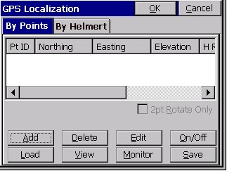
Add Method 1--Read GPS: This allows the user to collect measurements from the GPS receiver and average as many readings as preferred. Once the readings are complete, the software will present a dialog that displays the range and residuals of the averaged readings.
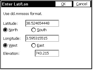
Add Method 2--Enter Latitude/Longitude: This allows the user to hand-enter known geodetic coordinates for the local position. The elevation should be the ellipsoid elevation in the jobs current units if a geoid model is not applied. If a geoid model is applied, then the elevation should be the orthometric elevation in the current job units. This method allows manual entry of a localization file without occupying points in the field. Note that you do not enter the decimal for decimal seconds.
If you use manual entry of a localization data set, it is important that you either utilize an existing base GPS receiver with the fixed antenna location that was used to survey the original geodetic positions, or that you set up your base on a known GPS position measured previously using that localization data set. Good survey practice would include checking into known positions to verify the quality of your hand-entered GPS localization, and verifying low residuals in the Localization screen. With all data pairs used for both horizontal and vertical control (none turned off), the resolutions for this data set would appear.
Add Method 3--From Raw File: This allows the user to use a point from the raw data file that has been previously collected via GPS. This is just like ōRead from GPSö except you are recalling a point previously measured and stored in the raw file. For this to work, you must have the base antenna in the same position as when the original raw file was collected, or you need to set your base antenna over a known coordinate from the original survey, and enter those original coordinates and the new base antenna height within the command Configure Base.
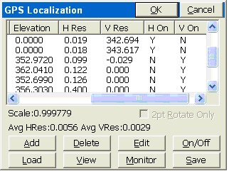
Note that in this example, it takes three horizontal control points, active ōH On = Yö to get horizontal residual results, and four vertical control points, active ōV On = Yö to get vertical residual results. You can on a trial basis remove different points from consideration both vertically and horizontally and watch the residuals of the remaining control points improve or degrade. In this way, if you have four or more total control points, you can determine the best combination to use as horizontal and vertical control.
Discussion of Localization Techniques
If you do a base localization by entering Latitude and Longitude or known coordinates on the designated coordinate system, then you do not need to add localization points. A base localization would put you on grid north and grid scale and would work for any new job where you are not trying to ōmatchö existing coordinates. However, any time you are working on a project that has existing coordinates, you will most likely need to do a Localization. Even if that existing job is supposedly on state plane, UTM or another known coordinate system, the project coordinates often fail to match grid scale and grid north exactly, requiring localization. When localizing, it is advisable to use at least three points for horizontal control and four points for vertical control, in order to get a measure of ōresidualsö or accuracy. The program will ōbest fitö a plane through all activated (H=On and/or V=On) control points. The residuals are how much each activated point is ōoffö of the plane surface. Because multiple elevation points may create a slightly ōtiltedö plane, some surveyors will verify that the vertical control has low residuals and is accurate using multiple vertical control points, then turn off all but one (V=Off) and use only the nearest vertical (elevation) as they progress through the job.
Note: The Scale Factor set in Job Settings, Units, will cause all GPS measurements to be adjusted by the scale factor. For GPS, scale factors can only be entered for 1-point localizations (base or rover). For multi-point rover localizations, the scale factor is computed by the localization and fixed. It appears ghosted under Job Settings, Units. When a scale factor is used for 1-point localizations, scaling occurs along the vector outward from the single localization point in the direction of the measured point. For GPS, the scale factor acts as a divisor. A scale factor of 0.9 would calculate the measured point 1/0.9 units further away from the single localization point. Therefore, it is recommended that you keep the scale factor set to 1.0. When configured to total stations, the scale factor is sometimes used to go ōground to gridö. When configured to GPS, the scale factor in Job Settings, Units is sometimes used to go ōgrid to groundö, to better match total station scaling. The scale factor is defined as ōground to gridö. To go ōground to gridö from high elevations, for example, it would be less than 1. It would multiply total station measurements and reduce them to grid. It would divide GPS measurements and expand them to ground. If your goal is to work on the specified state plane, UTM or other grid coordinate system, and you are planning to use a 1-point localization, then the scale factor should be set to 1, unless you are trying to match ōgroundö coordinates, where the coordinates are ōtrue northö but not ōtrue scaleö. In all other cases, matching ground coordinates with GPS is best accomplished with a multi-point rover-based localization. The resulting ōeffectiveö scale factor multipler will appear in the localization screen, such as the 0.999779 value shown in the last figure.
After a change in a localization file, any points measured in the field by GPS will be converted from Lat/Long to local coordinates by using the new localization file. For this reason, it is a good idea to re-convert older GPS measurements to the same, compatible coordinate system by going to Process Raw Data, option Process GPS, within the Cogo menu.
Geoid Files
The Geoid file is loaded onto SurvCE using Carlson X-Port. You first select the area of interest, then X-Port ōcarves outö the geoid for that area and downloads it to SurvCE. You set the Geoid file to use in Job Settings, GPS tab. The Geoid should be used principally with 1-point localizations. Starting with a known position for the base (or using a 1-point rover localization and approximate base position), the program will add or deduct the geoidal separation from the computed Z value on all measurements, and will match more closely to geoid-based surface elevations. The Geoid can also be used with multiple-point rover localizations, since the added accuracy provided by the geoidal calculation can reduce vertical residuals. This is true, however, only if the points being matched had Z values that, themselves, considered the geoid. Since you will get a best-fit plane that minimizes vertical residuals with or without use of the geoid, it is often not used with rover-based localizations.
Changing or Updating the Localization File
There are two ways to change a localization file: one is to edit an existing file by deleting elements, to add additional localization points. In either case, whenever a change in the ō.datö localization file is detected, you are prompted whether you would like to re-process any previously stored GPS points found in the raw file. A dialog appears.
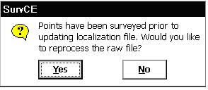
If you answer ōYesö, it takes you to the Process GPS command found within Cogo, Process Raw File.
Recalculating Stored GPS Points
There is no requirement to survey all localization points first, unless you are doing stakeout. For simple topo or data gathering, you can set up your base, survey in one or two localization points with the rover, then gather data in Store Points as needed. As you move cross country and encounter another known, or even unexpected control point, you can localize on it and add it to the list, verify residuals, and if the results are good, you can reprocess the raw file and keep your entire survey fully updated. If the residuals are disappointing, you can choose not to include the new point in the localization file. Either remove it or turn its H and V components off. You can also choose Process Raw File to recalculate all GPS measurements at any time.
Including the Base Position in the Localization File
To use the base in the localization, you should configure the base with the "Use Local Coordinates" option under "From Known Position". Here, you configure the base by entering the local point (5000,5000,100, etc.) and start a new localization file (or use an existing one if it applies). Then, at your rover, you can add more points to the localization as necessary.
Localization and the Raw File
If the scale for GPS is determined from the localization, a ōGPS Scaleö record of 1.0 and a ōLocalization Scaleö equal to the calculated scale appearing in the Localization screen will be written to the RW5 file.
Using the Localization File to Improve Base Localizations through Logging Static Data
The Localization File (.dat) typically applies to rover-based localizations. But if you did a ōRead GPSö on your base antenna position and then took GPS shots with no rover localization, and logged static data on the base in the meantime, it is possible to submit that logged information to the OPUS program and obtain an accurate base position. But is it too late to recalculate all the field shots taken earlier from the less accurate base? No. Follow this procedure: