The View menu is found next to the File menu in MAP view. Below you will find each feature described.
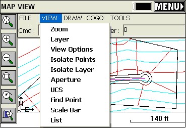
Zoom (Z):
Increase or decrease the apparent size of polylines and distances between points, in drawing area. The Zoom command options can also be accessed using the first five buttons from left-toolbar menu. The order of buttons, starting with the first top button, is: Extents, In, Out, Window, Previous. The menu also has Num which lets you enter in a point number and zoom to it.
Layer (LA):
This command manages layers and layer properties.
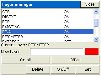
To add a new layer: Type in a new name into the New Layer edit box. The New button will appear at the bottom. Tap this button. If you type in a new layer name and the New button does not appear, then the layer name you entered contains invalid characters.
To set a layer current: Highlight the layer name in the list and then tap the Set button. You cannot set a layer current if that layer is turned Off. Turn the layer On first and then set it current.
To delete a layer: Highlight the layer name in the list and tap the Delete button. You cannot delete layers that contain objects. If you select a layer and the Delete button is not visible, then this layer contains objects.
To turn a layer On/Off: Highlight the layer name and tap the On/Off button. Objects on layers that are On will be visible, objects on layers that are Off are not visible.
On all: This button will turn all layers on
Off all: This button will turn all layers except the current layer off.
Color: Clicking on the color bar will bring up the color palette allowing you to set or change the layer color of the highlighted layer.
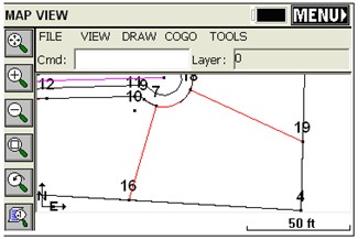
One of the main purposes of the Layer command is to permit the import, by DXF, of a drawing containing all possible polyline work to stake out (set out). Then you can reduce clutter on the drawing by turning layers off, leaving only the layers you want. You can then do the command Cogo, Interpolate Points, Polylines to Points and make point numbers out of all vertices (corners) of polylines where you need to set stakes. Then proceed with Stakeout by Points.
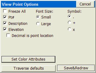
View Options (VO):
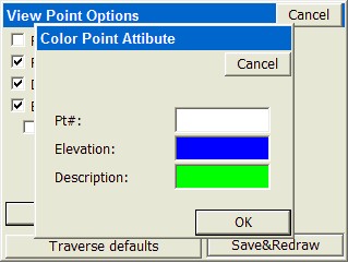
This command controls the appearance of point objects on screen. This is exactly the same as touching the lower left graphic icon. The routine displays the View Point Options dialog. Pt#, Description and Elevation toggles control whether these attributes are labeled with the points. If Freeze All is on, the points are placed on the map, without attributes. Available point symbols are: ".", "+", "x". The “Decimal is point location” toggle determines if the decimal point used in the display of elevations represents simultaneously the point location and symbol. This slightly reduces screen clutter.
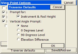
Small and Large toggles determine the size of font used to display the point object on screen. Set Color Attributes brings up the color palette (available only on color CE devices). This lets you choose the color of the point symbol, elevation and description text. The Traverse Defaults button brings up a dialog that has the settings for prompting each time for instrument and rod height and the vertical angle. This applies to the T for Traverse and SS for Sideshot commands that allow point calculation within the MAP Screen. For Cogo work, turn off Instrument/Rod Height and Vertical Angle prompting. For manual entry of actual field measurements, turn them back on.
Isolate Points (ISO):
This is another useful command to reduce screen clutter. If you have 500 points on the screen, you can isolate to only those points you wish to see, be entering a distinct point range, in the form 1-10, 22, 25-30, or a certain description. This would isolate to points 1 through 10, point 22 and points 25 to 30, and other points are “frozen”. Repeat the ISO command and enter the full point file range (or “all”) to restore all points.
Isolate Layer (IL):
Select any polyline layer and isolate it to keep that layer. Other polyline layers are turned off (frozen), but point layers are retained. Use the Layer command to turn layers back on as needed.
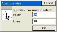
Aperture (AP):
Controls the size of the rectangle area used to select points or polylines from screen. Initially, the size in pixels is 40 units for points selection and 10 units for polylines selection. The routine displays the Aperture size dialog.
UCS (UCS) User Coordinate System Indicator:
This toggles the visibility of the UCS icon shown in the MAP screen.
![]()
Find Point (FND):
This command allows you to find a point on the MAP screen. Enter the point you want to find and a zoom height. If you enter a point that is not on the map, the dialog will warn you and allow you to enter another point number.
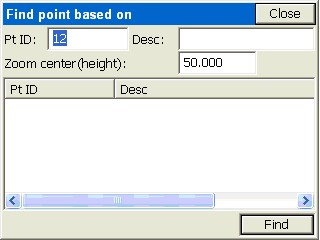
Click Find and the SurvCE zooms centers to the selected point at the entered scale.
Scale Bar (SB):
This toggles the visibility of scale bar on or off. The scale bar is normally shown at the bottom of the MAP screen.
List (LI):
This lists the layer, 2D or 3D status, Closed or Open status, perimeter (length), and area or projected area (if not closed).