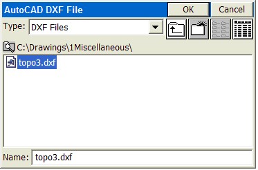
DXF File - Import DXF (IDXF)
Similar to the AutoCAD DXFIN command, will bring in polylines from AutoCAD, MicroStation and other CAD formats that can export data into a DXF file format. Points, text and blocks such as symbols are not imported. However, many software packages such as Carlson SurvCADD allow text to be converted into polylines – in which case the text will import for reference.
DXF FIle - Export DXF (EDXF):
The EDXF command, similar to AutoCAD’s DXFOUT command, will export a DXF file. It captures not only 2D and 3D polylines and their layer names but also exports all visible (layer on) points from the CRD file into AutoCAD “Point” entitites form (layer PNTS). All points and polylines that are visible (layers on) would be exported, not based on the current screen zoom, but based on the full extents of the drawing.
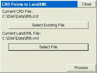
LandXML - CRD from Land XML (XML2CRD):
This command allows you to import points from LandXML format to SurvCE.
LandXML - CRD to Land XML (CRD2XML):
This command allows you to export points from SurvCE to LandXML format.
LandXML - Export Chain File to LandXML (CHAINXML):
This command allows you to export all the polylines from the current drawing created using Feature Codes, as LandXML chain objects into a LandXML file. For example, if you made strictly 3D polylines for break lines using descriptions such as EP for edge-of-pavement or DL for ditch line, then the 3D polylines can be exported as a LandXML chain file and used as break lines for contouring in other CAD programs. The combination of points and break lines can lead to optimal contouring. Most CAD packages will import linework using the DXF file approach, but many now recognize linework in LandXML “Chain” file format.
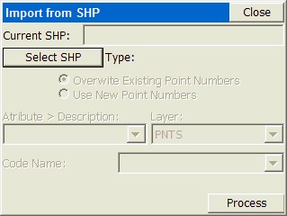
SHP File - Import Shape File (ISHP) (e.g. from ESRI):
This command allows you to import entities and also the associated attributes values from a SHP file. The routine displays "Import from SHP" dialog box. If the SHP file has POINT or POINTZ type, the entities will be stored into a CRD file. In the cases of an ARC, ARCZ, POLYGON or POLYGONZ SHP type, the entities will be stored into the current drawing. The attribute values will be stored into a *.vtt file. The routine requires a feature code name from the user, which will be used to store the name and the type of the attributes from the SHP file.
SHP File - Quick Import SHP (QISHP):
This command allows you to import entities from SHP files (used by most programs produced by ESRI). The routine displays the Import from SHP dialog shown below. POINT or POINTZ type entities will be stored in a CRD file. ARC, ARCZ, POLYGON, or POLYGONZ entities will be stored in the current drawing as POLYLINES.
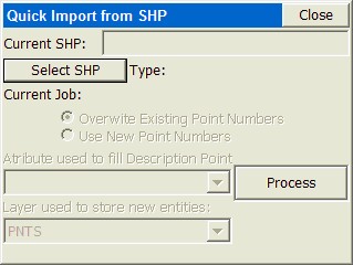
Current SHP: Displays the name of the SHP file that will be imported when this command is completed. Read-only, you must use the Select SHP button to specify the file name.
Select SHP: Tap this button to select a SHP file name.
Current Job: Available when importing coordinate data. Specify whether to Overwrite Exiting Point Numbers or Use New Point Numbers.
Attribute used to fill Description: Available when importing coordinate data. Lists the attributes in the currently selected SHP file. Select which attribute to use to fill out the Description field in the CRD file.
Layer used to store new entities: Available when importing geometry. Select the layer to store the new entities.
Process: Tap this button to begin the import process. If you are importing a large file, a progress bar at the bottom of the dialog will indicate the progress of the import.
SHP File - Export SHP File (ESHP):
This command allows you to export entities from the current drawing and also the associated attributes values, into a SHP file (or more accurately, multiple shape files). The routine will allow the user to select which entities will be exported, based on entity type and also based on the feature code name. The routine displays "Export to SHP" dialog box.
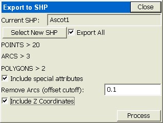
Click on Export All and Include special attributes and optionally the Z coordinates. If you have point, arcs (non-closed polylines in ESRI terminology) and polygons (closed poylines), all with one attribute, you will obtain up to nine files as shown below:
Ascot1_11.dbf
Ascot1_11.shp
Ascot1_11.shx
Ascot1_13.dbf
Ascot1_13.shp
Ascot1_13.shx
Ascot1_15.dbf
Ascot1_15.shp
Ascot1_15.shx
The selection of the Z coordinate places the 1 after the underline character. Otherwise, the file form would be, for example, Ascot1_1.shx (special attributes only). The “1” group represent points, the “3” group represent arcs (unclosed polylines) and the “5” group represent polygons (closed polylines). Within Export Shapefile, the field name in the dbf file is expanded to handle up to 254 characters.
SHP FIle - Quick Export SHP (QESHP):
This command allows you to export polylines and/or points to an SHP file. The dialog that displays will have the following options:
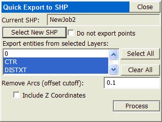
Current SHP: Displays the name of the SHP file that will be created when this command is completed. Read-only, you must use the Select new SHP button to specify the file name.
Select new SHP: Tap this button to select a SHP file name.
Do not export points: When this option is checked, only polylines are exported to the SHP file.
Export entities from selected Layers: Lists the layers in the current map. You may select certain layers for export.
Select All: Selects all layers in the list.
Clear All: Clears all selected layers in the list.
Remove Arcs (offset cutoff): Specifies the maximum distance that a vertex on a polyline segment will deviate from the original arc.
Include Z Coordinates: When this option is checked, elevation data (or Z coordinates) will be included in the SHP file.
Process: Tap this button to begin the export process. If you are exporting a large file, a progress bar at the bottom of the dialog will indicate the progress of the export.
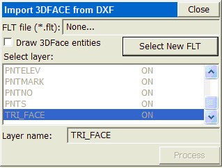
DTM Import - DTM from DXF (TDXF):
Allows you to import 3DFACE entities from a DXF File and save them as a triangulation (FLT) file and also draw them as 3D faces.
DTM Import - DTM from Land XML (TXML):
Allows you to import 3DFACE entities from an XML File and save them as a triangulation (FLT) file and also draw them as 3D faces.
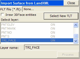
The DTM file is stored in SurvCE as an FLT file and can be used for commands such as Elevation Difference (obtaining cut/fill by comparing field measurements to the DTM).
The 3DFaces are placed on a layer (TRI_FACE by default), and that layer can be turned off and removed from view. If you choose E for Erase, you can pick the 3DFace entities and erase them on command. There is no particular value to seeing the 3D Faces, so it is not recommended that they be drawn. The main value is to capture the FLT (triangulation) file for use in Elevation Difference.
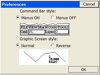
Preferences (SETT):
This allows the user to turn on/off the pull-down MAP menus. The graphic screen style of normal or reverse (solid dark) background is set here.
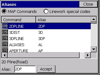
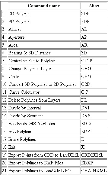
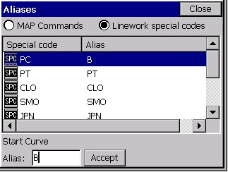
Command Aliases (AL):
Brings up a list of commands in the MAP mode for which the user can substitute an alias. If you would prefer to type A for Area rather than AR, you can substitute “A” as an alias for AR. Three commands will not accept substitutes: Inverse, Traverse and Sideshot (I, T and S). In addition to commands, you can toggle over to the “Linework special code” option, and substitute aliases codes for the default special codes such as PC, PT and END (used to control linework using feature codes). As an example, you could choose the “X” or “..” to End a line, or use “CS” for curve start instead of PC.
Quick Save (QS):
Saves the current DXF file without prompting for the file name.
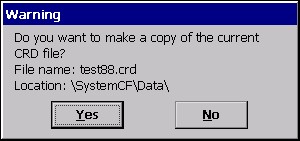
Save As(CRD) (SCRD):
Saves the current coordinate file to the location you choose as a backup copy.
Exit (X):
This exits the MAP and CAD session and brings you back to the Menu screen. Hitting the MENU button in the top right corner does the same thing.
Help (H):
Launches the interactive Help screen describing various MAP screen commands. Scroll up and down to review.