|
Process Raw File
|
|
Process Raw File
|
Carlson SurvCE creates a raw file (.RW5) that contains various lines of survey data similar to a surveyors' field book. This data contained in the RW5 file will vary depending upon whether Total Stations, Robotics or GPS is used during the survey. The name of the RW5 file will default to the specified job name. This command enables viewing and editing of the raw survey data, as well as traverse closure and adjustment computations for the survey, for both total station and GPS raw data. If total station shots are involved, a graphical representation of the traverse can also be viewed using this command.
Total Station and GPS Use
Total Station adjustments are conducted distinctly from GPS adjustments (Process GPS). If you wish to adjust your GPS first for control, and then calculate your total station traverse, then first select Process GPS. Then use Process No Adjust, or Compass rule, as desired.
Process Raw File Operations: Total Station, GPS, Reporting, Editing
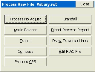
There are four “classes” of raw file processing that you can do. You can process or draw your total station traverse, you can report out the Direct-Reverse measurements, you can Process GPS and you can Review and Edit the RW5 file.
Total Station Adjustments
If you wish to adjust or draw a total station traverse, you would choose any of the following: Process No Adjust, Angle Balance, Transit, Compass, Crandall or Draw Traverse Lines. All of these commands have the same 4-tab menu system, oulined below.

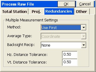
The Backsight Reciprocal options treat reciprocals “special”. A foresight to point 15 from a setup on 14, followed by a backsight from 15 to 14, makes a pair of “reciprocal” readings. The backsight “reciprocal” reading can be ignored (for its impact on recalculating the occupied point), or the Elevation component of the reciprocal measurements can be averaged, or both the Elevation and Distance can be averaged, to recalculate the setup (occupied point) coordinates. The program will calculate reciprocals for backsight direct (BD) records. First set Backsight Reciprocals to Average Elevation. Then if you foresight from 2 to 3, for example, then occupy 3 and backsight 2, the stored BD record will lead to an averaged delta Z calculation for point 3 within Process No Adjust or any of the other adjustment options. If the Tolerances entered above are exceeded, then warning screens appear during the processing.
Note: If there are significant redundancies in a traverse (reciprocal readings, D&R sets, multiple measurements to the same point from different setups, multiple tie shots into control) then it is recommended that the raw file be processed in a Network Least Squares program back at the office, such as SurvNet which is an add-on to Carlson Survey or SurvCADD.
Process No Adjust
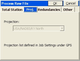
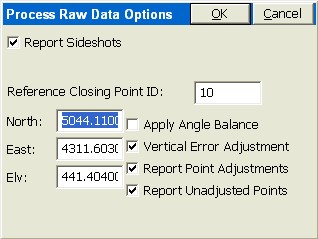
This command processes the RW5 file and computes coordinate values for the surveyed data. No angle balance or traverse adjustment is applied. The Process Raw Data Options dialog shown below appears after selecting Process No Adjust.
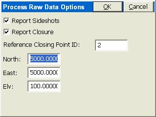
You can report the traverse only or compute all measurements by clicking on Report Sideshots. If you click on Report Closure, then you need to specify a “Reference Closing Point ID”, which is the point that the last traverse point is closing to, or trying to match. The “Reference Closing Point ID” is not a point in the traverse—it is the point the traverse is trying to close on. It can be entered as a point ID or a coordinate.
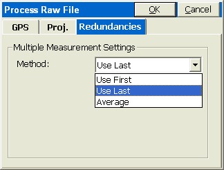
Note: To preserve coordinate values of the initial setup and backsight, particularly with D&R measurements involved, it is recommended that Redundancies by set to Average by Distance Measurement, if averaging is used.
Pressing OK leads to the calculation and the report screen for Process No Adjust.
Angle Balance
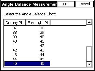
This process method applies an angle balance to the traverse lines when calculating the coordinates. The angle balance takes the angular error divided by the number of traverse lines and adjusts the angle of each traverse line by the calculated amount. The angular error is the difference between the angle balance shot and a reference angle. The program will prompt for the traverse shot to use as the angle balance shot. The measured direction between the occupied point and the foresight point in the specified angle balance shot is then compared to a reference angle. The reference angle is specified as a bearing, azimuth or by a traverse line defined by entering a “from point” and a “to point”. The angle balance process is initiated by selecting the angle balance option from the process raw file menu.

The Angle Balance Measurement dialog shown in figure appears. Say our traverse started at 24, traversed up to 25, then around a loop and back to 24 (point 45). If point 45 was the end point or closing shot, the traverse leg from 45 to 46 could be the angle balance shot in this case. It is very common, for example, in closed-loop traversing to take a closing angle shot from the closing point (45) by measuring the angle along the first traverse leg (24 to 25). That is what occurred in the case of this sample traverse.
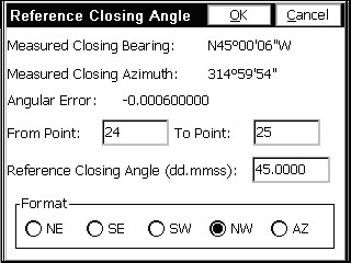
Next, the Reference Closing Angle dialog appears. Enter the bearing or azimuth of the reference angle, or by defining the reference angle with points by entering in the desired point numbers in the From Point and To Point fields. If using bearing or azimuth, enter in the bearing in DD.MMSS format and then selecting the correct quadrant from the format field located at the bottom of the dialog. Once the reference angle has been defined, then the angular error display will update with the calculated angular error. The measured closing bearing and measured closing azimuth is displayed at the top of the dialog box. If the reference angle has been defined by point numbers, then the reference closing angle field will update and display the defined angle. There is no need to select a format from the format field if point numbers are used.
Pressing the OK button, or the enter key, will execute the angle balance process and the process results will be displayed. The results display shows the closure results before angle balance and after angle balance.
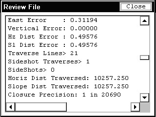
The angular adjustment applied to each traverse leg is also displayed along with unadjusted angles and adjusted angles for each traverse leg. The adjusted coordinates are written to the coordinate file replacing the unadjusted coordinate values.
Transit, Compass, Crandall Adjustments
These methods apply the selected rule to the traverse lines when calculating the coordinates. After adjusting the traverse points, the sideshots can also be recalculated. The closure error is calculated as the difference between the specified ending point and a reference point. The ending point is specified in the initial dialog.
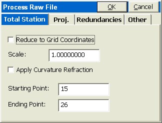
You can change the ending point to correspond to the point in the traverse that closes back to the existing reference point. In our case, point 26 is our final shot, and is closing to an existing point 10.
The reference point is specified by point ID or by entering the northing, easting and elevation of the reference point.
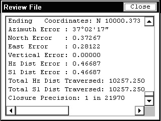
The process results show varying information depending on selected options from the Process Raw Data Options dialog box.
If Angle Balance is clicked on, you will be asked for the “closing angle” shot and the reference closing angle screen will appear, which you complete as described in the Angle Balance section above. The closure method will be applied to the coordinates before or after angle balance, depending if angle balance is clicked on.
The routine will conclude, for all three closure methods, by displaying the final, adjusted angles, distances and coordinates. The coordinate values in the CRD file will change as a result of the closure adjustment.
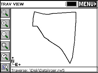
Draw Traverse Lines
This command employs the same 4-tab screen as Process No Adjust and the other adjustment routines. It displays a preview of the traverse configuration by drawing lines between the traverse points. To start the command select Draw Traverse Lines from the Process Raw Menu. Enter in the beginning and ending points to draw on dialog and press enter. An example of the results is shown in this next figure. To exit the preview screen, select the menu button at the top right of the screen.
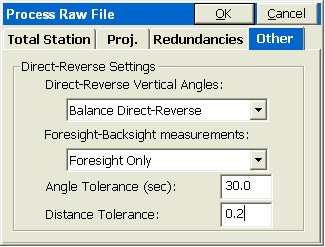
Direct-Reverse Report
This command creates a report of direct and reverse shots along with the resulting averaged shots. The residuals are the difference between the measurement and the final average. Shown below is a direct and reverse report for a shot taken from point 1, backsighting point 4 and foresighting point 100.
Direct-Reverse Report
Observations
Type Setup FSight HorzAngle Distance Vertical
BD 1 4 359.5958 279.8760 89.4827
BR 1 4 179.5945 279.9490 270.1114
FD 1 100 336.1603 211.2160 75.0056
FR 1 100 156.1601 211.2150 284.5848
BD 1 4 359.5948 279.9500 89.4824
BR 1 4 179.5942 279.9500 270.1111
FD 1 100 336.1608 211.2150 75.0052
FR 1 100 156.1601 211.2170 284.5850
Reduced Sets
HorzAngle Residual FS Diff. BK Diff.
336.1610 0.0004 0.0002 0.0013
336.1619 0.0005 0.0007 0.0006
Vertical Residual Diff.
75.0104 0.0004 0.0016
75.0101 0.0004 0.0018
Distance Residual Diff.
211.2155 0.0002 0.0010
211.2160 0.0002 0.0020
Means
HorzAngle SD Distance SD Vertical SD
336.1615 0.0004 211.2158 0.0002 75.0103 0.0001
Process GPS
If GPS measurements are detected in the RW5 file, then the Process GPS button becomes available within Process Raw. The main dialog appears.
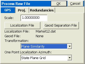
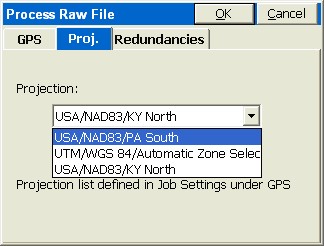
The Transformation Types are Plane Similarity (recommended default) and Rigid Body, No Scale and for One Point Localizations, north can be defined by State Plane Grid or Geodetic North.
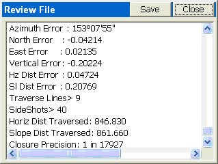
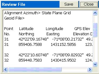
When all settings are correct, select OK. The results appear in the Review File dialog.
Edit Raw (RW5) Survey File
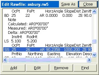
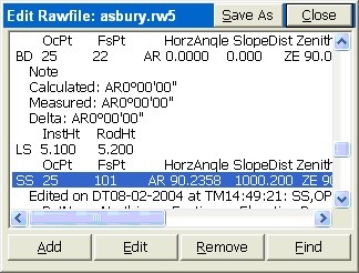
The Raw Survey Notes can be reviewed and edited by clicking Edit Rw5 File. A fairly typical application is to edit or add rod height records, when changes in rod heights were not recorded. The editor allows changes to virtually all measured data, but will record the original data as a note (that cannot be deleted). Entries can be Added, Edited or Removed, but even if removed, original data is retained in a note.
To Edit, just highlight the desired line.
Click the Edit button, and the line appears in a specially formatted Edit dialog, tailored to the type of data selected.
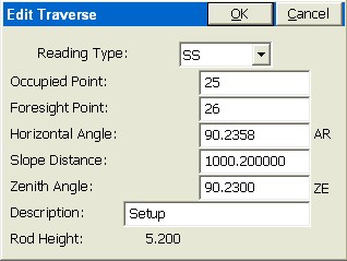
You can change, for example, the foresight point to 101 by clicking into the Foresight Point dialog box, entereing 101, then pressing OK. The data is changed, with a note showing the original data and indicating when it was edited.
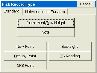
If you click Add, you get to select from a variety of record types.
The Network Least Squares tab is a special option that let’s you designate measurements for eventual processing in the Carlson SurvNet program (office network least squares software).
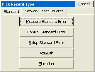
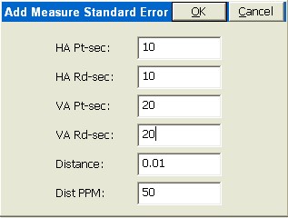
If, for example, you pick Measure Standard Error, you can enter errors appropriate for your instrument, and reduce the entries required to process the network least squares adjustment when back in the office.
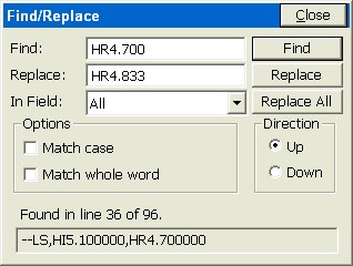
The Find option let’s you globally change any set of characters in the raw file. It is useful for changing a series of descriptions to a new description for purposes of “field-to-finish” drawing. It is also useful for finding a particular shot that you recall by number or description. Here’s how you might change all 4.700 rod heights to 4.833, in case you learned that the rod had an extra attachment measuring 0.133 in length. Direction “Up” would replace all occurrences of HR4.700 prior to the currently highlighted line in the raw file. You can limit the search by use of the “In Field” option by selecting only Descriptions, Notes or Points, or search All records.