Tools Menu: Edit Process Raw File
11.11 Carlson Raw Editor
FUNCTION:
The Carlson Raw Editor routine is used to edit and re-run traverse courses, compute closures, and do traverse adjustments. The
Carlson Raw Editor option uses the raw editor common to other Carlson Software
products.
Activate
the Carlson Raw Editor by
picking from the Tools
menu; by pressing
[Alt][T],
[E], [A];
or by typing the two-letter command
ER
at any data entry prompt.
 |
NOTE: By default, "Sight" Survey uses the Carlson Raw Editor
and .RW5 files for Traverse Closure, Deed Check, and
adjustments (including adjustments other than Network Least Squares).
The C&G Raw Editor is available for data transfer and Network
Least Squares. If you want to transfer a C&G raw file (.CGR)
from your collector and then run a Compass, Crandall,
Transit, or No Adjust, you need to download the .CGR file,
then open the Carlson Raw Editor and import the C&G file (using
Tools > Import Raw Data > C and G). |
 |
HINT: When called from
"Sight" Survey, the Raw Editor window is a Primary Focus
window. You cannot access other "Sight" Survey windows or
routines while the Raw Editor is active. |
In this
section we cover:
Record Types and
Editing Records
The Carlson Raw Editor
routine reads or creates a raw data (.RW5) file that contains various lines of
data (records) that could be likened to a surveyor's field book. You can
specify point coordinates, job information, notes, and the angles and distances
that make up traverse or sideshots records. Once the raw data is created
or read it can be processed/reduced to coordinates that are stored in the
current coordinate (.crd; .cgc; .mdb; .zak) file.
The raw
file can also be created or appended using the Enter & Assign (EA
-
Section 6.01), Traverse (TR
-
Section 7.09), Sideshot (SS
-
Section 7.07), and Inverse (IN
-
Section 7.01) commands. To store the data
inputs from these commands into a raw file, first toggle on the Raw File
Recorder ON/OFF command (RR -
Section 3.14) on the File menu.
It's
also possible to enable the raw file storage automatically when you open a new
job by checking the Enable Raw Storage option in the lower left corner of
the New "Sight" Survey Job dialog.
The raw
files created by TDS data collector programs are also compatible without
conversion. Use the C&G Data Transfer program (see
Section 11.08) to download the file. Within the Carlson raw data
editor, use Tools > Import Raw Data for converting raw data from other
formats. Available import formats include:
-
C&G
-
CalTrans
-
Carlson
-
Fieldbook
-
Geodimeter
-
Leica
-
Nikon
-
SDMS
-
Sokkia/SDR
-
SurvCE Archive
-
TDS
-
Trimble
When
you select the Carlson Raw Editor
command you will also to specify the name of the raw data (.RW5) file.
The current coordinate file is automatically used. To change the current
coordinate file, use the Project File Manager command (FM
- see
Section 3.13) under the File menu before
starting this command. If no coordinate file is current, the program will prompt
you to set the current coordinate (.CRD) file.
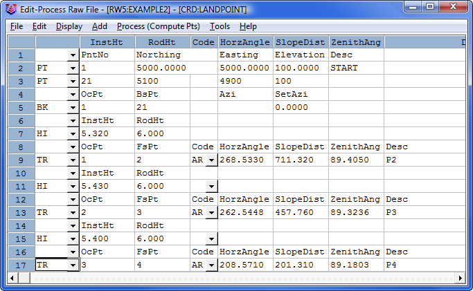
Edit-Process Raw
> Carlson Raw Editor uses a spreadsheet for editing the raw data as
shown. Each row of the spreadsheet is represented by a number located at the far
left side of the editor. Various messages and reports often reference possible
problems with the data by this row number. Each row of the spreadsheet
represents one record of data. There are 14 types of data records. The type of
data record is shown in the first column. Different record types use different
numbers of columns. Whenever the data record type changes between rows, a record
header is added to the spreadsheet that describes each column of data in the
following row. To edit the raw data, simply highlight the cell and type in the
new value. To change the type of record, pick on the down arrow in the first
column and choose a new data type from the list. To delete a row, highlight any
cell in the row and hit the [Delete] key or choose
Edit > Delete Row.
Records can be added pressing the [Insert] key, pressing the down arrow key from
the last line in the spreadsheet, or by choosing one of the record types from the
Add menu.

The different record types are described below.
|
Code |
Record Type |
|
TR |
Traverse: The traverse record contains the occupied point number, foresight point number,
angle mode, horizontal angle, distance, vertical angle and description. When
processed, this record will calculate and store the coordinates for the
foresight point. Traversing also moves the setup by making the traverse
foresight point the next occupied point and the traverse occupied point becomes
the next backsight point. The different angle codes are NE for northeast
bearing, SE for southeast, SW for southwest, NW for northwest, AZ for azimuth,
AL for angle left, AR for angle right, DL for deflection angle left and DR for
deflection angle right. To set the angle code, pick on the Code down arrow
(q) and
choose from the list. The horizontal and vertical angles should be entered as dd.mmss. For example, 45.2305 is 45 degrees, 23 minutes and 5 seconds. The
vertical angle can be shown as vertical angle (0 degrees level), zenith angle
(90 degrees level) or elevation difference. The vertical angle mode is set in
the Display menu. The distance mode is also set in the Display menu as either
slope or horizontal distance. The description field is used as the foresight
point description.
|
|
SS |
SideShot: The sideshot record is the same as the traverse record except that sideshot does
not move the setup.
|
|
BK |
BackSight:
The backsight record contains the occupied point number, backsight point number,
backsight azimuth and the set azimuth. This record should precede any traverse
and sideshot records that use this setup. If no backsight point is entered, the
program uses the backsight azimuth to turn angles from. The Set Azimuth is the
circle reading of the instrument when sighting the backsight. A Set Azimuth of
zero is the default.
|
|
HI |
Instrument and Rod Height:
This record sets the instrument and rod heights used in elevation calculations.
This record should precede any traverse and sideshot records that you want the
heights applied to.
|
|
PT |
Point (or Store Point): The
store point record consists of a point number, northing, easting,
elevation and description. When processing, this data will be
stored as a point in the coordinate file. If the first Occupied
point and/or the initial Backsight point are not defined in the
coordinate file set for processing to, both points will need to be added
to the RW5 file as PT (Store Point) records.
|
|
EL |
Elevation
Only: This record sets the elevation in the CRD file for the specified point number.
Often used when an existing point with good vertical control is being traversed
through. Using this record type for the point would keep the elevation from
changing on the existing point regardless of the measurement data.
NOTE: This command is not on the Type pull down but may
be manually entered into the Type field on a blank record.
If entered manually you must type the command in upper case letters.
|
|
GPS |
GPS:
This record contains the Latitude and Longitude of a point as measured by GPS
surveying equipment using Carlson SurvCE data collection software. This record
has additional information tied to it such as localization files, geoid files,
coordinate projection systems etc. This record has its own processing routine in
the Process pull down within the editor. Processing procedures are discussed in
the Process (Compute Pts) pull down documentation.
|
|
NAME |
Traverse Name: This record acts as an identifier for the group of records that make up a
traverse. All the records after the NAME record belong to that traverse up to
the next NAME record or the end of the file. This record allows you to have
multiple traverses in one raw file. When running one of the Process commands,
the program will bring up a list of all the traverse names. Simply choose which
traverse to process. If you have only one traverse in the raw file, then you
don't need the NAME record.
|
|
DS |
Description:
The description record is an additional note that appears in the spreadsheet
editor and printouts. This record can contain various information that is
recorded in data collectors during field operations. This data can vary
from user, temperature and general data to each line of data associated
with Set
Collection. When "Sets" of data collected using various brands of data
collection software is converted/imported into the raw editor, the actual
measurements made during the spinning of the angles and distances are recorded
as DS records and the mean value of the angle and distance is recorded as a SS
record. DS records are not used in processing.
|
|
AZ |
Azimuth Only:
Applies to SurvNET, the Network Least Squares analysis and adjustment
routine. NOTE: This command is not on the Type pull
down but may be manually entered into the Type field on a blank
record. If entered manually you must type the command in upper
case letters.
|
|
CSE |
Control
Standard Error: Applies to SurvNET, the Network Least Squares analysis and adjustment
routine.
|
|
SSE |
Set-up
Standard Error:
Applies to SurvNET, the Network Least Squares analysis and adjustment
routine.
|
|
MSE |
MSE (Measurement
Standard Error: Applies to SurvNET, the Network Least Squares analysis and adjustment
routine.
|
|
CL |
Closing Shot: The closing shot record is the traverse record where the foresight point is the
closing point for the traverse. This record is used by the adjustment commands
in the Process menu. There should be only one CL record in each Traverse loop
(Name Record) in the raw file. If there is no CL record, the process adjustment
routines will prompt for which shot is the closing shot. The closing shot can
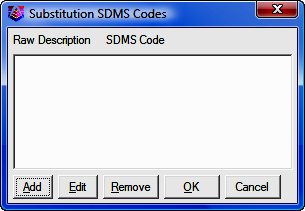
also be define in the field by using special codes defined in the Open Settings
found under the File pull down within the editor. Please refer to the Open
Settings documentation for more information on these codes.
|
|
AB |
Angle Balance:
The angle balance record is the measurement data observed that closes the angles
of the traverse. Typically this record is the measurement data recorded from the
closing shot to the initial backsight point. The backsight could be either
external or internal to the traverse. The Angle Balance routine in the
Process menu
uses this record and compares the angle between the occupied point and foresight
point of this record with a user-specified reference angle. There should be only
one AB record in the raw file. If there is no AB record, then the
Angle Balance
routine will prompt for which shot to use as the angle balance.
|
|
CL+AB |
Closing Shot and Angle Balance: This record is used as both the closing shot and angle balance records.
|
|
FD |
Foresight Direct: The foresight direct is a traverse record used in a direct and reverse set. When
the program finds one the of direct-reverse measurement records, it will look
for the other three records to complete the set.
|
|
FR |
Foresight Reverse: The foresight reverse is a traverse record used in a direct and reverse set.
|
|
BD |
Backsight Direct: The backsight direct is a traverse record used in a direct and reverse set.
|
|
BR |
Backsight Reverse: The backsight reverse is a traverse record used in a direct and reverse set.
|
Raw Data Editor
Menus
File Menu
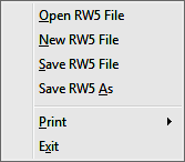
Open RW5 File
This command prompts for a
RW5 file to load into the editor.
New RW5 File
This command clears the editor spreadsheet.
Save RW5 File
This saves the
RW5 file. If the file hasn't been named you will be prompted for
the file name and the location to save the file. After you perform the first
save, this command acts as a quick save and saves the file to the name and
location specified during the initial saving of the file.
Save RW5 As
This command saves the raw editor data in the spreadsheet to a
RW5 file
and always prompts for file name and location to save.
Print > Raw Data
A sample of
the raw data report is shown below. This report shows the data from the
raw editor spreadsheet.
Raw File> c:\data\survey.RW5
CRD File> c:\data\survey.crd
   Note
   Survey Example
   PntNo   Northing Easting   Elevation Desc
   1       5000     5000    100       START
   OcPt    BsPt     SetAzi
   1
   InstHgt RodHgt
   5.32    6.0
   OcPt    FsPt     HorzAngle SlopeDist ZenithAng Desc
TR 1       2     AR 268.5330  711.420   89.4050   P2
   InstHgt RodHgt
   5.43    6.0
   OcPt    FsPt     HorzAngle SlopeDist ZenithAng Desc
TR 2       3     AR 262.5448  457.760   89.3236   P3
   InstHgt RodHgt
   5.4     6.0
   OcPt    FsPt     HorzAngle SlopeDist ZenithAng Desc
TR 3       4     AR 208.5710  201.310   89.1803   P4
TR 4       5     AR 247.1657  497.120   88.5235   P5
TR 5       6     AR 277.4835  223.980   90.2926   P6
TR 6       7     AR  92.4113  233.880   90.2746   P7
   InstHgt RodHgt
   5.42    6.0
   OcPt    FsPt     HorzAngle SlopeDist ZenithAng Desc
TR 7       8     AR 261.2756  387.250   91.4405   CLOSE
SS 7       19    AR 289.3456  112.450   91.3423   SS1
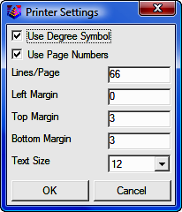
Print > Print Settings
This dialog has settings for the report functions.
Left Margin settings are in characters. Top Margin and
Bottom Margin settings are in lines. At standard line spacing with a
Text Size of 12, there are 66 Lines/Page.
Exit
Exits the raw file editor.
Edit Menu
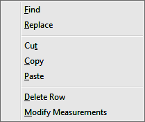
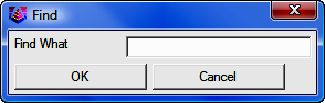
Find
This
command allows you to
search and find a particular word, letter, numeric value or a combination of
all. Letter case does not matter.
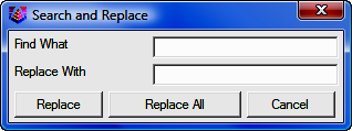
Replace
This command allows you
to search and replace a particular word, letter, numeric value, of a combination
of all. Letter case does not matter. It also provides further options to
Replace individual items one at a time or
to Replace All.
Cut
This is
a standard windows cut command. It removes data from editor and places it
in the windows clipboard.
Copy
This is
a standard windows copy command. It copies selected data to windows
clipboard.
Paste
This is
a standard windows copy command. It inserts cut or copied data from the windows
clipboard.
Delete Row
This command deletes the row containing the active cursor or cell. You can
delete a row by placing the cursor in any of the cells in the row that you wish
to delete, or by picking on the row number at the far left of the editor.
 |
WARNING! You may also delete a row by
placing the cursor in the row and pressing [Delete].
Use caution! There is no Undo command.
To delete the contents of a single cell, select the contents before
pressing [Delete]. |
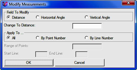
Modify Measurements
This option allows for a change in distance, horizontal angle or vertical
angle by a specified amount for the entire file or for a specified point number
or line number range. To modify a measurement, choose which field to modify
and
enter the change in either distance or angle in dd.mmss format. Next choose how
to apply the modification. If All is selected, the change will be applied to all
records in the specified field. If By Point Number is chosen, enter the point
number or range of numbers in the Range of Points field. If By Line Number is
chosen, then define the area for the change by specifying the Start and
End line.
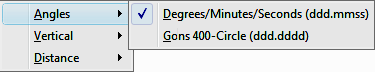
Display Menu
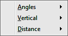
Angles
This option chooses the angle format between
Degrees/Minutes/Seconds
(ddd.mmss) and Gons-400 Circle (ddd.dddd). This setting applies to
the angles in the spreadsheet editor as well as the angle format for reports.
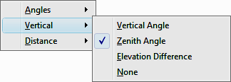
Vertical
The options contained in this menu allow for specifying the type of
vertical measurement information you will input or is contained in the RW5 file.
The Vertical Angle selection assumes the barrel or scope of the instrument is
level when reading 0 (zero). With this setting, the vertical component of a
measurement record will have a header of VertAng. The Zenith Angle selection,
most commonly used, assumes the barrel/scope to be level when reading 90. Using
this setting results in a header of ZenithAng. Elevation difference displays the
elevation difference between the occupied and foresight points. If the Distance
option is specified as Slope, this elevation difference will be used to
calculate the horizontal distance of the measurement. The header for this record
is ElevDiff. The None selection assumes all distances are horizontal distances
and removes the vertical component for a measurement from the editor. Switching
modes can be performed at any time.
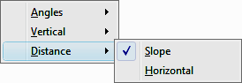
Distance
This
option controls the display of either Slope or Horizontal Distances. Changing
the display results in the distance data adjusting to reflect the correct value
for the selection made. The vertical data: VertAng; ZenithAng;
or VertDiff is
used to convert the distance value when changing this display option.
Add Menu
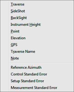
Traverse
Adds
a traverse record (TR) to the spreadsheet editor. The new record will be insert
above the row that contains the active cell unless this row is the last row in
the file. If so, you will be prompted to insert above or below the current row.
SideShot
Adds a sideshot record (SS) to the spreadsheet editor. The new
record will be inserted above the row that contains the active cell unless this
row is the last row in the file. If so, you will be prompted to insert above or
below the current row.
Backsight
Adds a backsight (BK) to the spreadsheet editor. The new
record will be inserted above the row that contains the active cell unless this
row is the last row in the file. If so, you will be prompted to insert above or
below the current row.
Instrument Height
Adds an instrument height (HI) record to the editor. This record contains both the instrument and rod height setting. The new
record will be inserted above the row that contains the active cell unless this
row is the last row in the file. If so, you will be prompted to insert above or
below the current row.
Point
Adds a point (PT) record to the editor.
Inserting a blank record allows for manual input to define the coordinates for
the point. The new
record will be inserted above the row that contains the active cell unless this
row is the last row in the file. If so, you will be prompted to insert above or
below the current row.
Elevation
Adds an elevation (EL) record to the editor. The new record
will be insert above the row that contains the active cell unless this row is
the last row in the file. If so, you will be prompted to insert above or below
the current row.
GPS
Adds a GPS record to the editor. The new record will be insert above
the row that contains the active cell unless this row is the last row in the
file. If so, you will be prompted to insert above or below the current row.
Traverse Name
Adds a traverse name (Name) to the editor. The new record
will be insert above the row that contains the active cell unless this row is
the last row in the file. If so, you will be prompted to insert above or below
the current row.
Note
Adds a note (DS) record to the editor. Note records are for
information display and do not effect processing except for two special notes
which are:
Elevation: 2D
Elevation: 3D
These special notes set the elevation mode for processing for the records that
follow the note. The raw editor starts in 3D mode. The Elevation: 2D note will
switch processing to 2D mode and the Elevation: 3D note will switch the mode
back to 3D. In 2D mode, the processing will not set the elevations in the
coordinate file.
Reference Azimuth
This record applies to SurvNET, the optional Network Least Squares
analysis and adjustment routine.
Control Standard Error
This record applies to SurvNET, the optional Network Least
Squares analysis and adjustment routine.
Setup Standard Error
This record applies to SurvNET, the optional Network Least
Squares analysis and adjustment routine.
Measurement Standard Error
This record applies to SurvNET, the optional Network
Least Squares analysis and adjustment routine.
Process (Compute Pts) Menu
This menu contains tools to process raw data by various methods. The calculated
coordinates are stored to the active specified
coordinate file. The
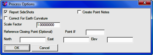
options for processing are specified within either the Process Options dialog
box or the Closure Options dialog box. This dialog box is
displayed before processing data, using any of the available methods, with the
exception being the Least Squares method.
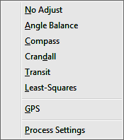
No Adjust
No Adjust means
that no angle balance or traverse adjustment will be applied. Options are
specified in the Process Options dialog.
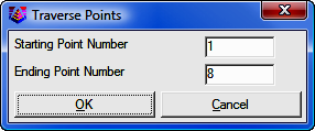
After picking
[OK] on the process
options dialog, a Traverse Points dialog appears for entering the starting and
ending point numbers.
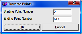
The program reads the raw file to set the defaults for these point numbers
which are used to calculate the closure. The difference between the ending point
and the reference closing point is the closure error and the sum of the traverse
distances from the starting to the ending point is used as the total distance
traversed. After picking [OK] for the second dialog, the program starts processing
the raw file from the top record down. The result is displayed in the Standard
Report Viewer which can save, print or draw the report.
Angle Balance
This process method applies
an angle balance to the traverse lines when calculating the coordinates. Options are
specified in the Process Options dialog.
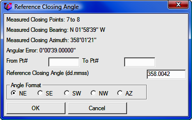
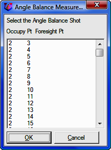
The
angle balance takes the angular error divided by the number of traverse lines
and adjusts the angle of each traverse line by this amount. The angular error is
the difference between the angle balance shot and a reference angle. The angle
balance shot is specified as a type AB or CL+AB record in the raw file. If no
AB
record is found in the raw file, then the program will prompt for which traverse
shot to use as the angle balance shot. The angle from the angle balance shot is
calculated as the angle from the occupied point to the foresight point. The
reference angle can be specified as a bearing, azimuth or by two point numbers
in the dialog shown.
The angle balance report shows the unadjusted points, the unadjusted closure,
the angular error, the adjusted points and then the adjusted closure. Typically
but not always, applying the angle balance correction will improve the traverse
closure.
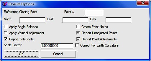
Compass, Crandall,
Transit
These process methods apply the selected rule to the traverse
lines when calculating the coordinates. After adjusting the traverse, the
sideshots are also recalculated. The closure error is calculated as the
difference between the closing shot and a reference point. The closing shot is
specified as a type CL or CL+AB record in the raw file. If no
CL record is found
in the raw file, then the program will prompt for which traverse shot to use as
the closing shot. The foresight point is used as the closing coordinate. The
reference point can be specified by point number or by entering the northing,
easting and elevation. The process results report shows the unadjusted points,
closure error, adjustments to each traverse point and adjusted point.
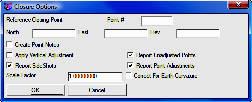
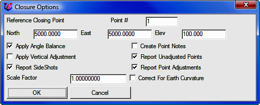
Options are
specified in the Closure Options dialog.
Specify
the closing Point # or enter North, East, and (optional)
Elevation coordinates. After picking [OK]
on the process
options dialog, a Traverse Points dialog appears for entering the starting and
ending point numbers.
The program reads the raw file to set the defaults for these point numbers
which are used to calculate the closure. The difference between the ending point
and the reference closing point is the closure error and the sum of the traverse
distances from the starting to the ending point is used as the total distance
traversed. After picking [OK] for the second dialog, the program starts processing
the raw file from the top record down. The result is displayed in the Standard
Report Viewer which can save, print or draw the report.
Least Squares
This
Least Squares routine is simpler least squares adjustment, not SurvNET
which is a robust network least squares adjustment routine. If you want to
use the features from SurvNET, close the editor and select Tools > Network
Least Squares from the "Sight" Survey menus, then load your RW5 file into
SurvNET. See
Section 11.12 for SurvNET instructions.
From the raw file data, this routine makes initial calculations for
the coordinate points in the traverse. The constraints of the routine are:
all angle readings must be in angle right mode; and the coordinates of the starting and the ending points must be known.
The routine begins with a dialog for specifying the reference closing
coordinates and any scale factors to apply to the distance measurements. The
Reference Closing Point is the last point in the traverse, whose coordinates
must be known.
Specify
the closing Point # or enter North, East, and (optional)
Elevation coordinates. After picking [OK]
on the process
options dialog, a Traverse Points dialog appears for entering the starting and
ending point numbers.
This routine applies a least-squares adjustment to the data stored in the .RW5 file. The closing errors are
distributed among the other points, using the "Method of Least Squares" (Ref :
Wolf, P.R. and Ghilani, C.D., 1996, "Adjustment Computations", John Wiley and
Sons, NY,Third Edition). After the adjustment, the rest of the raw file is
processed to recalculate the sideshots.
The least squares process report shows the input data and the results. For
each point, the amount adjusted and the standard error in X and Y are reported. The
Reference Standard Deviation is based on the sum of the residuals and the
initial estimated standard errors. The Chi-Squares test is a goodness-of-fit
test that checks the reference standard deviation with the least-squares model. If this test fails, there may be a blunder in the measurement data or the
initial estimated standard errors were too low or too high.
GPS
The
process GPS routine allows
for reduction of GPS records that reside in a raw (*.RW5) file from latitude,
longitude and WGS84 Ellipsoid Height to State Plane or local coordinates. When
selected, the GPS Settings dialog will appear as shown below.
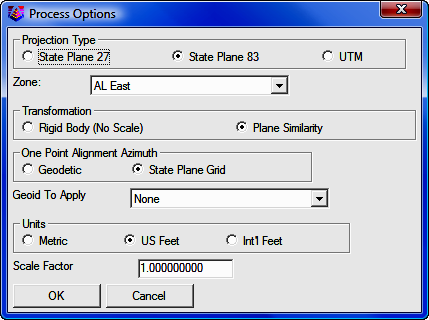
Projection Type
This setting defines the datum coordinate system to be used for converting the Latitude,
Longitude and WGS84 Ellipsoid height collected from the GPS receiver into
Cartesian coordinates. The supported projection types are: State Plane 83;
State
Plane 27; and UTM.
Zone
For State Plane projections,
you must select the correct state zone that you are working in. For UTM, the
Automatic Zone option will have the program automatically user the program
automatically use the correct UTM zone for your location. Otherwise for UTM, you
can manually set a specific UTM zone. This manual option applies to working on
the border between zones and you want to force the program to always use one of
those zones.
Transformation
The
transformation in SurvCE's Align Local Coordinates command can either be by plane similarity or
rigid body methods. The difference is that the rigid body method does a
transformation with a translation and rotation and without a scale. The plane
similarity does a rotation, translation and scale. This option only applies when
two or more points are used in Align Local Coordinates or the Localization
routine in SurvCE.
One Point Alignment Azimuth
This
option applies to the rotation when using one point in Align Local Coordinates
or the Localization routine in SurvCE. For this alignment method, the state
plane coordinate is translated to the local coordinate. Then the rotation can
use either the state plane grid or the geodetic as North. No scale is applied in
this transformation. The state plane and geodetic true north diverge slightly in
the east and west edges of the state plane zone. This option allows you to
choose which north to use: Geodetic; or State Plane Grid.
Geoid to Apply
The supported geoids include:
-
Geoid99 (USA)
-
Geoid03 (USA)
-
World (EGM96)
-
(World (OSU91A)
-
Australia
(AUSGeiod98)
-
Belgium (BG03)
-
Canada (CGG2000)
-
Canada (HT 2.0)
-
Canada (HT 1.01)
-
Canada
(GSD95)
-
Caribbean (CARIB97)
-
Finland (2000)
-
France(RAF-98)
-
Great Britain (OSGM02)
-
Ireland (OSGM02_ROI)
-
N.
Ireland (OSGM02_NI)
This option will account for the geoid undulation in determining the
orthometric elevation of the measurement. The definition of the geoid model as
currently adopted by the national Geodetic survey is the equipotential surface
of the Earth's gravity field which best fits, in a least squares sense, global
mean sea level. Orthometric elevation measurements are used in survey
calculations. In order to convert ellipsoid heights (He) as measured by GPS into
orthometric elevations (E0), you must provide for a correction between the
GPS-measured ellipsoid (reference ellipsoid) and a constant level gravitational
surface, the geoid. This corrections is the geoid undulation (Ug). The formula
is He=Eo + Ug.
Carlson applies the Geoid model by subtracting the Geoid undulation from the
GPS elevation. The resulting elevation is then used and displayed. In practice,
the Geoid model is most applicable to two types of alignment scenarios. One of
these types is when setting up the base over a know point and having no
alignment control points. The other is when there is one alignment control
point. When using multiple alignment control points, the Geoid model is not as
important because Carlson can model the elevation difference which can generally
pick up the local Geoid undulation.
Units
Coordinates can be reduced
into one of three available units: Metric; US Feet; or International Feet.
Scale Factor
For most
applications, the Scale Factor should be set to 1.0. The scale factor represents
the “combined” grid/elevation factor that reduces ground distances to grid. After converting the LAT/LONG from the GPS records to state plane coordinates
and applying the coordinate alignment (Localization) file, the Scale
Factor is applied as the final adjustment to the coordinates. This adjustment is
used on the X, Y, and not the Z. The Scale Factor is applied by dividing
the distance between the coordinate and a base point by the Scale
Factor. The coordinate is then set by starting from the base point and moving in
the direction to the coordinate for the adjusted distance. The base point is the
first point in the alignment (Localization) file. If there are no points
specified in the alignment file, then 0,0 is used as the base point. If using an
alignment file (Localization File) this value will be automatically calculated
and displayed. Manual entry of a scale factor is also permitted.
Use Alignment File For Localization
After
selecting [OK]
in the Process Options dialog, the
Alignment File dialog is displayed.
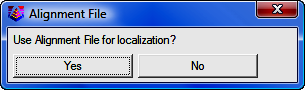
This file is typically created by SurvCE (Carlson's Data
Collection System) using the Localization routine or by Carlson Field Using the
Align to Local Coordinates routine. This file (*.DAT) contains the parameters to
transform the derived State Plane coordinates to the defined local coordinates.
If you select [Yes] you will be asked to
select the alignment file using a standard Windows file selection dialog.
At the
end of the process, the coordinates will be written to the current coordinate file and a report will be presented in the Carlson editor for
saving or printing purposes.
Process Settings
This option
allows for the setting of user preferences and tolerances to be used during
processing and generation of reports.
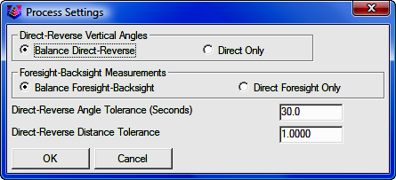
Direct-Reverse Vertical Angles
This option determines how to handle direct-reverse vertical angle
measurements when processing.
Balance Direct-Reverse
will take the mean of the direct-reverse measurements and use this value when
processing the file. Direct
Only will only use the direct measurement to the point for processing.
Foresight-Backsight Measurements
Balance Foresight-Backsight allows for
averaging in the foresight and backsight measurements when using direct-reverse
sets. The
Direct Foresight Only option will average the foresight measurements only of
a direct-reverse set.
Direct-Reverse Angle Tolerance (Seconds)
This is the tolerance that the angle measured by the direct measurements and the
angle measured by the reverse measurements in a direct-reverse set must fall
within.
Direct-Reverse Distance Tolerance
This
setting allows for user input of desired tolerance
values for multiple measurements. Exceeded tolerances will be displayed on the
process results report. The residual values
of the measurements will be shown on the process results report. The data to be averaged can be either the
Distance Measurements or the Coordinates.
Tools Menu
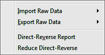
Import
These routines convert raw data from other formats into the
current Carlson RW5 format. The converted raw data will be added to the end of
any existing data in the editor. In many cases, the raw data file to import can
be downloaded directly from the data collector or instrument using the Data
Collectors command. The following supported formats (along with their
standard file extension) are listed here.
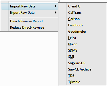
-
C&G (.CGR, .RAW, .TXT, *)
-
CalTrans (.DMP)
-
Carlson (.RW5)
-
Fieldbook (.FBK) - from Softdesk, Land Development Desktop or Civil 3D.
-
Geodimeter (.OBS, .RAW, JOB, *)
-
Leica (.GSI, .RAW, GRE): This reads the Leica raw file in Wildsoft,
Liscad, 10-20-30-40, C&G, or GeoComp format. There are options to specify
direct-reverse shot order if any and to convert from International Feet to
Leica US Feet.
-
Nikon (.TRN, .RAW)
-
SDMS (.PRJ, *)
-
SMI (.RAW)
-
Sokkia SDR (.SDR, .RAW, *)
-
SurvCOGO (.RAW or .TXT)
-
SurvCE Archive (.SC5) - When downloading an RW5 file from SurvCE using
SurvCOM, there's an option to copy the RW5 file to a SC5 file as a read-only
backup
-
TDS (.RW5, .RAW)
-
Trimble (.DC)
Export
These routines convert the Carlson raw data (.RW5)
file to other formats. The following file formats are supported.
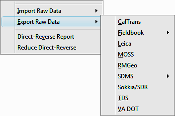
-
Sokkia (.SDR)
-
TDS (.RW5, .RAW)
-
VA Dot (.TOP)
Direct-Reverse Report
This
routine creates a report of direct and reverse shots along with the resulting
averaged shots. Any tolerance specified in the Process Settings>Direct-Reverse
Settings section, that is exceeded will be displayed in this report. The
residuals are the difference between the measurement and the final average.
Reduce Direct-Reverse
This
routine processes the direct and reverse shots and simplifies the raw file by
replacing the sets of direct and reverse shots with the resulting average
traverse record.
Format of the raw data
(.RW5) file
The
Carlson raw data format is a comma delimited ASCII file containing record types,
headers, recorded data and comments. The format is based on the RW5 raw data
specification, with the exception of angle sets. Angle sets are recorded as BD,
BR, FD and FR records to allow reduction of all possible combinations.
Essentially, these records are identical to a sideshot record.
Backsight Record
Record type: BK
Field headers:
|
OP |
Occupy Point |
|
BP |
Back Point |
|
BS |
Backsight |
|
BC |
Back Circle |
Sample(s):
BK,OP1,BP2,BS315.0000,BC0.0044
Line of Sight Record
Record type: LS
Field headers:
|
HI |
Height of Instrument |
|
HR |
Height of Rod* |
*GPS
heights may be recorded to phase center or ARP depending on GPS make.
Sample(s):
LS,HI5.000000,HR6.000000
LS,HR4.000000
Occupy Record
Record type: OC
Field headers:
|
OP
|
Point Name
|
|
N
|
Northing (the header is
N space)
|
|
E
|
Easting (the header is E space)
|
|
EL
|
Elevation
|
|
--
|
Note
|
Sample(s):
OC,OP1,N 5000.00000,E 5000.00000,EL100.000,--CP
Store Point Record
Record type: SP
Field headers:
|
PN
|
Point Name
|
|
N
|
Northing
|
|
E
|
Easting
|
|
EL
|
Elevation
|
|
--
|
Note
|
Sample(s):
SP,PN100,N 5002.0000,E
5000.0000,EL100.0000,--PP
Traverse /
Sideshot Record / Backsight Direct / Backsight Reverse / Foresight Direct /
Foresight Reverse
Record type: TR / SS / BD / BR / FD / FR
Field headers:
|
OP
|
Occupy Point
|
|
FP
|
Foresight Point
|
|
|
(one of the
following)
|
|
AZ
|
Azimuth
|
|
BR
|
Bearing
|
|
AR
|
Angle-Right
|
|
AL
|
Angle-Left
|
|
DR
|
Deflection-Right
|
|
DL
|
Deflection-Left
|
|
|
(one of the following)
|
|
ZE
|
Zenith
|
|
VA
|
Vertical angle
|
|
CE
|
Change Elevation
|
|
|
(one of the following)
|
|
SD
|
Slope
Distance
|
|
HD
|
Horizontal Distance
|
--, Note
Sample(s):
TR,OP1,FP4,AR90.3333,ZE90.3333,SD25.550000,--CP
SS,OP1,FP2,AR0.0044,ZE86.0133,SD10.313750,--CP
BD,OP1,FP2,AR0.0055,ZE86.0126,SD10.320000,--CP
BR,OP1,FP2,AR180.0037,ZE273.5826,SD10.315000,--CP
FD,OP1,FP3,AR57.1630,ZE89.4305,SD7.393000,--CP
FR,OP1,FP3,AR237.1612,ZE270.1548,SD7.395000,--CP
GPS
Record
type: GPS
Field headers:
|
PN
|
Point Name
|
|
LA
|
Latitude (WGS84)
|
|
LN
|
Longitude (WGS84,negative for West)
|
|
EL
|
Ellipsoid elevation in meters*
|
|
--
|
Note
|
*GPS heights may be recorded to phase center or ARP depending on GPS
make.
Sample(s):
GPS,PN701,LA42.214630920,LN-71.081409184,EL-21.8459,--C
P /Brass Disk
Alphabetical
listing of Record Types
|
BD
|
Backsight Direct
|
|
BK
|
Backsight
|
|
BR
|
Backsight Reverse
|
|
FD
|
Foresight Direct
|
|
FR
|
Foresight Reverse
|
|
GPS
|
GPS
Position in Lat (dd.mmss) Lon (dd.mmss - Negative for West) and WGS84 Ellipsoid
Elevation in meters
|
Alphabetical listing of Field Headers
|
AD
|
Azimuth Direction ( 0 for North,1 for
South)
|
|
AL
|
Angle-Left
|
|
AR
|
Angle-Right
|
|
AZ
|
Azimuth
|
|
BC
|
Back Circle
|
|
BP
|
Back Point
|
|
BR
|
Bearing (this
field will be recorded as N123.4500W)
|
|
BS
|
Backsight (when back point is not
defined)
|
|
CE
|
Change Elevation
|
|
DL
|
Deflection-Left
|
|
DR
|
Deflection-Right
|
|
DT
|
Local Date (MM-DD-YYYY)
|
|
E
|
Easting (the header is E space)
|
|
EC
|
Earth Curvature (0 for off, 1 for
on)
|
|
EL
|
Elevation (GPS value is ellipsoid
elevation in meters)
|
|
EO
|
EDM Offset
|
|
FE
|
Foresight Elevation
|
|
FP
|
Foresight
Point
|
|
HD
|
Horizontal Distance
|
|
HI
|
Height of Instrument
|
|
HR
|
Height of Rod
|
|
LA
|
Latitude
|
|
LN
|
Longitude
|
|
N
|
Northing (the header is N space)
|
|
OC
|
Occupy
Point Coordinates
|
|
OP
|
Occupy Point
|
|
PN
|
Point Name
|
|
SD
|
Slope Distance
|
|
SF
|
Scale Factor
|
|
TM
|
Local Time (HH:MM:SS)
|
|
UN
|
Distance Unit (0 for feet, 1 for meter, 2
for US feet)
|
|
VA
|
Vertical Angle
|
|
ZE
|
Zenith
|
|
--
|
Note
|
Traverse Examples
|
 |
|
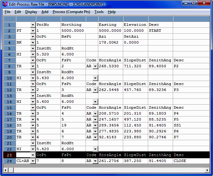
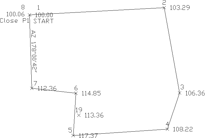
This first example is a closed
traverse with an internal backsight of azimuth 178° 00' 42" |
Use the
functions under the Add menu to create and fill out the raw file as shown
here.
Notice
that the record from point 7 to 8 is set as a CL+AB record. This tells the
program that point 8 is the closing point and that the angle from 7 to 8 is the
closing angle. For traverse adjustment, the closing reference point is 1 and the
closure error is the difference between point 1 and point 8. For angle balance,
the reference closing angle is 358° 00' 42" (178° 0' 42" + 180°). The angle balance
error is the difference between this reference angle and the angle from points 7
to 8.
Now
let's process using Compass adjustment with Angle Balance. Choose
Compass under the Process menu and fill out the dialogs as shown.
Process Results 05/23/2002 10:06
Raw file>
CRD file> C:/Program Files/Simplicity Sight Survey 2009/xporttmp.crd
Scale Factor: 1.00000000
Correct for Earth Curvature: OFF
Starting Point 1: N 5000.00 E 5000.00 Z 100.00
BackSight Azimuth: 178°00'42"
Point Horizontal  Zenith   Slope   Inst  Rod   Northing   Easting   Elev
No.   Angle       Angle    Dist    HT    HT
Description
2     AR268.5330  89.4050  711.32  5.32  6.00  5038.43    5710.27   103.29
P2
3     AR262.5448  89.3236  457.76  5.43  6.00  4587.89    5791.20   106.36
P3
4     AR208.5710  89.1803  201.31  5.40  6.00  4397.30    5726.43   108.22
P4
5     AR247.1657  88.5235  497.12  5.40  6.00  4363.08    5230.59   117.37
P5
19    AR289.3456  91.4405  112.45  5.40  6.00  4471.32    5260.88   113.36
SS1
6     AR277.4835  90.2926  223.98  5.40  6.00  4586.54    5245.67   114.85
P6
7      AR92.4143  90.2746  233.88  5.40  6.00  4613.25    5013.33   112.36
P7
8     AR261.2756  91.4405  387.25  5.42  6.00  5000.09    4999.97   100.06
CLOSE
Closure Results (Before Angle Balance)
Starting Point 1: N 5000.00 E 5000.00 Z 100.00
Closing Reference Point 1: N 5000.00 E 5000.00 Z 100.00
Ending Point 8: N 5000.09 E 4999.97 Z 100.06
Azimuth Error : 341°38'22"
North Error   : 0.09061
East Error    : -0.03007
Vertical Error: 0.05953
Hz Dist Error : 0.09547
Sl Dist Error : 0.11251
Traverse Lines> 7
SideShots> 1
Horiz Dist Traversed: 2712.29
Slope Dist Traversed: 2712.62
Closure Precision: 1 in 28409
Compass Closure
Adjusted Point Comparison
       Original           Adjusted
Point# Northing  Easting  Northing  Easting   Dist  Bearing
2      5038.445  5710.269 5038.440  5710.294  0.025 S 79°46'08" E
3      4587.914  5791.222 4587.907  5791.263  0.042 S 79°46'08" E
4      4397.319  5726.469 4397.310  5726.517  0.049 S 79°46'08" E
5      4363.044  5230.628 4363.032  5230.693  0.067 S 79°46'08" E
6      4586.509  5245.681 4586.496  5245.755  0.075 S 79°46'08" E
7      4613.178  5013.335 4613.163  5013.416  0.083 S 79°46'08" E
8      5000.017  4999.905 5000.000  5000.000  0.097 S 79°46'08" E
Max adjustment: 0.097
Starting Point 1: N 5000.00 E 5000.00 Z 100.00
BackSight Azimuth: 178°00'42"
Point Horizontal Zenith  Slope  Inst Rod  Northing  Easting  Elev
No.   Angle      Angle   Dist   HT   HT
Description
2     AR268.5326 89.4050 711.34 5.32 6.00 5038.44   5710.29  103.29
P2
3     AR262.5434 89.3236 457.76 5.43 6.00 4587.91   5791.26  106.36
P3
4     AR208.5704 89.1803 201.30 5.40 6.00 4397.31   5726.52  108.22
P4
5     AR247.1657 88.5235 497.09 5.40 6.00 4363.03   5230.69  117.37
P5
19    AR289.3456 91.4405 112.47 5.40 6.00 4471.28   5260.97  113.36
SS1
6     AR277.4839 90.2926 223.99 5.40 6.00 4586.50   5245.75  114.85
P6
7      AR92.4130 90.2746 233.88 5.40 6.00 4613.16   5013.42  112.36
P7
8     AR261.2758 91.4405 387.27 5.42 6.00 5000.00   5000.00  100.06
CLOSE
Shown above is the resulting process report. The angle balance had an error
of 39 seconds which was divided among the 7 traverse sides. The Compass Closure
shows how each traverse point was adjusted and then the resulting adjusted
angles and distances.
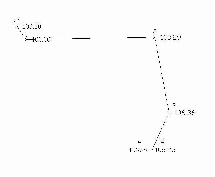
Here is another layout of the last example that shows an external backsight
setup. In this case there are two known points. Point 1 is the starting point
and point 21 is the initial backsight. The setup could also use a backsight
azimuth (ie north azimuth for example) instead of a backsight point number.
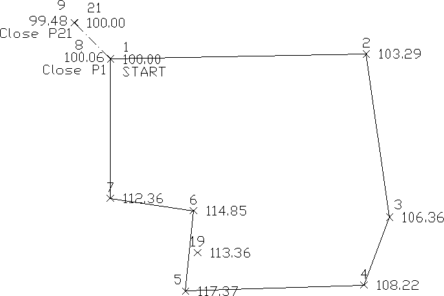
The closing record setup has changed from the last example. In this example,
the shot from 7 to 8 is the closing shot with point 8 as the closing point. The
closing reference point is still point 1. The angle balance shot is from 8 to 9
and the reference angle is from 1 to 21.
|
 |
|
Example of an open traverse |
The traverse starts from the known point 1 and ends at the known point 14. In
this case there is no angle balance shot. The closing shot is from 3 to 4 with
point 4 being the closing point. Point 14 is the closing reference point.
The closing record setup has changed from the last example. In this example,
the shot from 7 to 8 is the closing shot with point 8 as the closing point. The
closing reference point is still point 1. The angle balance shot is from 8 to 9
and the reference angle is from 1 to 21.
Here is an example of an open traverse.
Compass Report from Open Traverse example:
Process Results
Raw file> d:/scdev/data/tsurvey.RW5
CRD file> d:/scdev/data/tsurvey.crd
Compass Closure
Adjusted Point Comparison
       Original         Adjusted
Point# Northing Easting Northing Easting Distance Bearing
2      5013.76  5711.18 5013.78  5711.13 0.047    N 63d21'19" W
3      4560.69  5776.42 4560.72  5776.35 0.078    N 63d21'19" W
4      4372.46  5705.08 4372.50  5705.00 0.091    N 63d21'19" W
Point Horizontal Vertical Slope  Inst Rod Northing Easting Elev
No.   Angle      Angle    Dist   HT   HT
Description

2     AR133.5324 89.4050  711.27 5.32 6.00 5013.78 5711.13 103.29
3     AR262.5506 89.3236  457.74 5.43 6.00 4560.72 5776.35 106.36
4     AR208.5712 89.1803  201.30 5.40 6.00 4372.50 5705.00 108.22
The traverse starts from the known point 1 and ends at the known point 14. In
this case there is no angle balance shot. The closing shot is from 3 to 4 with
point 4 being the closing point. Point 14 is the closing reference point.