File Menu
3.13 Project File Manager (FM)
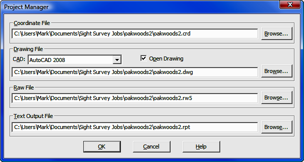
FUNCTION: The Project File Manager routine is used to change the current "Sight" Survey file set.
Activate the Project File Manager routine by picking from the File menu; by pressing [Alt][F], [M]; or by typing FM at any data entry prompt.
At first glance, this routine might be confusing. Why would you want to change the drawing file or the coordinate file while you are in the middle of a job? Why would you want to change a raw data file or a text output file? The Project File Manager allows you to combine elements from various files into one body of work without actually combining the data files.
Consider for example, a scenario in which you have a job containing all of the elements of a topographic site survey of an existing tract of land. You have loaded this as your current job. Your company's engineering design team has produced another file of proposed improvements; perhaps parking lot and building layouts. Now you must combine the data into a single drawing but you really don't want to merge the data files into a single job. Perhaps all they need to show is an outer boundary and contours. How can you do this?
You start by opening the topographic job, then launch the Project File Manager from the file menu. Under the Drawing File section, select the proposed site improvements drawing as the new drawing file and check the Open Drawing box. When you click [OK] you will be able to insert drawing elements into the new drawing from the old drawing file. You inverse around the property boundary and run contours and you're done.
Similarly there may be times when you need to change a coordinate file to use points from another file to insert drawing elements into your current project, but you don't want to actually import the points into the project. Accomplish this by temporarily changing the Coordinate File.
The Raw File referenced by the Project Manager is not the same as the raw data file you may have from your data collector. This raw file is actually created by "Sight" Survey as you enter in data, and is used in traverse adjustment using the Tools > Edit Process Raw Files > Carlson Editor routine (ER - Section 11.11). If you are checking several traverses or deeds, you might want to create a separate raw file for each tract.
The Text Output File contains everything that goes into the Text Output window. there may be times when you want to create a report file that contains only certain information but not the entire output. If you set up a new Text Output File you can create a specific report that does not include previous calculations and data.
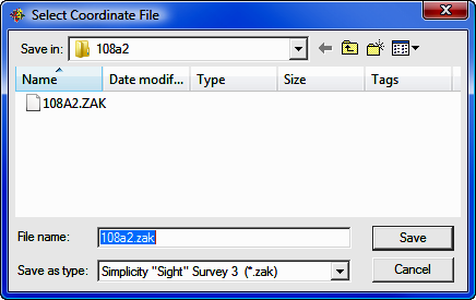
[Browse]: The [Browse] button is also an element common to all the options. Clicking on [Browse] will open a file selection dialog. The Save as type automatically reflects only the file types that are available for each particular option. Other than the Save as type setting, the window function is identical for all options and therefore will only be discussed once.
Save in: Click [q] to select the drive and folder or root folder location containing the job files. Typically, the default location will be the Sight Survey Jobs folder under your Documents folder. Use the lower window to further refine your search and select the desired job folder. Once the Job folder is open, click on the desired file and then click [Save] (or double-click the desired file).
File name: If you are creating a new file (coordinate, drawing, raw, or text output) type in the new filename here and select the file type in the Save as type field. Only valid file types will be presented for your selection and the chosen type will automatically determine the filename extension to add to the file name.
|
|
HINT: If you create a new coordinate file, be aware that the original file is closed when the new one opens which results in an empty coordinate file. To populate an empty coordinate file you may use: the Enter and Assign routine (EA - Section 6.01); the Import ASCII Files routine (see Section 3.08); or the Import Coordinate File routine (see Section 3.09). |
Save as type: Use this field to select the proper type for the file. Only valid file types will be presented for your selection and the chosen type will automatically determine the filename extension to add to the file name.
Coordinate File: Click [Browse] to select a new coordinate file. It may be a file of any supported type: Carlson Numeric; Carlson Alphanumeric; C&G Numeric; C&G Alphanumeric; Sight Survey 3; or LDD (Autodesk Land Desktop).
Drawing File: Click [Browse] to select a new drawing file.
CAD: Select the CAD version for the new drawing file. (If you are referencing an existing drawing, the drawing will automatically open in the CAD format under which it was last saved.)
Open Drawing: Check this box to open the new drawing when you leave this routine.
Raw File: Click [Browse] to select a new raw file.
Text Output File: Click [Browse] to select a new coordinate file.
Once you have completed your file specifications, click [OK] to activate the changes.