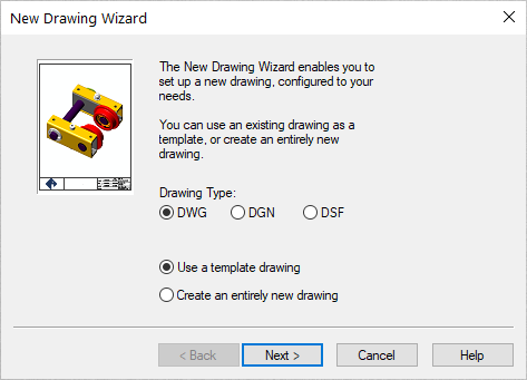
- If you get the Start Page, pick New Drawing.
- If you get the Startup Wizard dialog box, click New.
- If you are taken directly into CAD, click the File --
New command.
NOTE: If you want to consistently use the Startup Wizard, issue the Settings -- Carlson Configure -- General Settings and enable the Use Startup Wizard option. Click OK to dismiss the dialog boxes. The Startup Wizard will be used the next time the software is started.
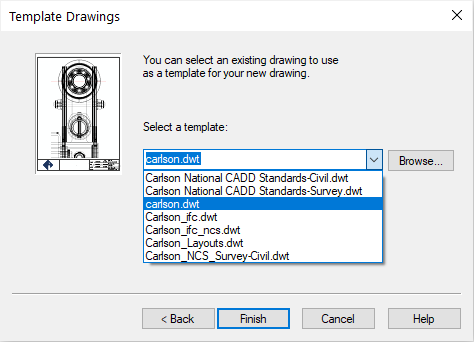
- Choose the DWG document type and the desire to base the
document on a Drawing Template as illustrated
below and then click Next >:
- Choose the carlson.dwt as illustrated below
(or surv.dwt if carlson.dwt is not available) and click
Finish:
- We can now begin the more pertinent settings for the project to
come based on some preliminary settings that should be similar to
the default scenario shown below:
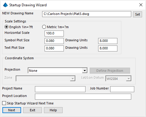
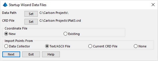
Click Set at the top of the dialog box, and enter in a NEW Drawing Name called Plat3. Verify that the other settings match the settings shown below, and click Next. - You will see the Startup Wizard Data Files dialog to
set/confirm where to store data and indicate an information source
for points/coordinates. Set/match the values as shown below and
click Next:
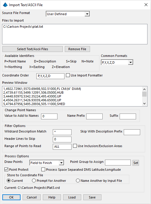
- The
Import Text/ASCII File dialog box appears. Our source is the
same file as in Lesson
2 (e.g. the ASCII-based Plat.txt
file). Click the Select Text/ASCII Files button
and navigate to and choose the C:\Carlson
Projects\Plat.txt file and click Open when ready. Set the
other values as shown in the dialog box below paying particular
attention to the Draw Points toward the bottom of
the dialog box and click OK when ready:
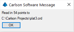
- When you complete the import, the following dialog box appears
(click OK to dismiss):
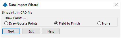
- A Draw Points confirmation dialog box
displays. Set/confirm the Field to Finish option, and click
Next:
- If this is your first time running Field-To-Finish, then the program will prompt to select a Field Code Definition file. In this case, select the C:\Carlson Projects\Settings\carlson.fld file and click Open when ready.
- A dialog box now appears with a warning that some codes have
two descriptions:
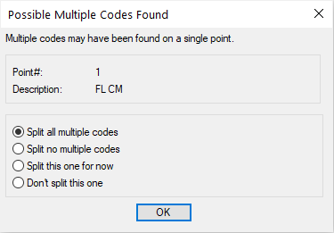
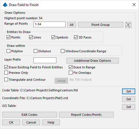
The command is asking whether these codes are to be treated as two separate descriptions, or as one description that has a space in it. Choose the Split all multiple codes to tell the command that codes with spaces are really two separate descriptions and click OK. - We are about ready to place the Field to Finish data into the
drawing. Take a moment to review (and optionally set) the values
shown below:
- Let's review/set some additional options. Click
Additional Draw Options to display the dialog box
below:
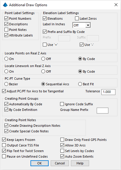
Set as shown above. Click OK for the Additional Draw Options and then click OK for the Draw Field to Finish dialog box.
Verify the Survey module is loaded by clicking Settings -- Carlson Menus -- Survey Menu.
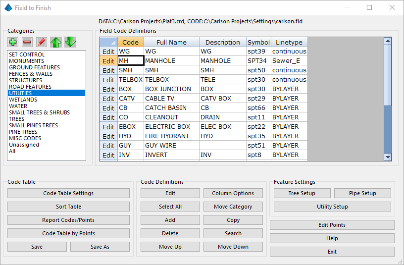
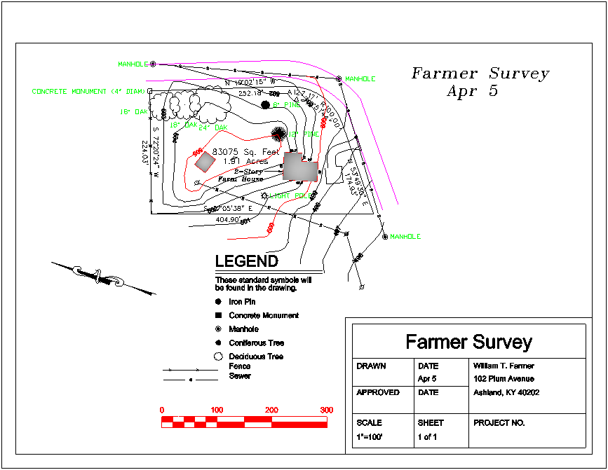
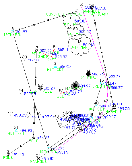
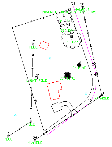
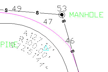
The display window shows a list of point codes, such as IP for iron pin and FL for fence line, that are converted to special symbols and linetypes by Draw Field to Finish. For an example of how the codes are used, look at the sewer line running from point 52 to 53 to 54 (the southernmost point), which is based on a field code of MH. Select the Utilities category and select the MH (for Manhole) code as shown above, and then click Edit. The following dialog box is displayed:
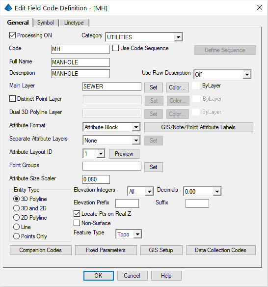
The MH code has several attributes that are used by Draw Field to Finish. For this code, Draw Field to Finish:
- places the manhole on layer SEWER
- labels a text description of MANHOLE underneath the symbol (Descriptions can be upper or lower case)
- Click on the Symbol tab and notice that it draws a manhole using the symbol SPT34
- Click on the Linetype and notice that it draws a sewer line with the letter S (for Sewer)
Other codes have different attributes:
- LP is set only to draw a symbol and text (Light Pole), but not to draw linework
- FL (for fence line) is set to draw linework but not corner symbols or points descriptions
The "Carlson.fld" Field to Finish code table is provided with Carlson Software. This table shows one possible system, but with likely far too many codes for a field crew to remember. You can make your own code table by:
- choosing the Code Table Settings option from the Field to Finish dialog box
- choosing the Set button at the top right, and,
- selecting the New or the Existing tab from the top of the Specify the Code Definition File dialog box.
- PNTS
- PNTELEV
- SPOT
Exit the Layer Manager when done.
Mode: break polyline at removal
Select polyline segment to remove [Options]: Pick the segment from 9 to 10
Select polyline segment to remove (Enter to end): Pick the segment from 10 to 15
Select polyline segment to remove (Enter to end): press Enter
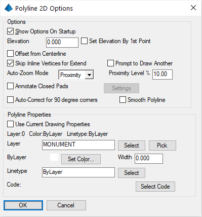
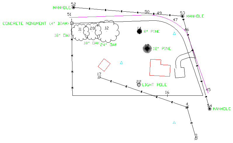
To draw the correct polyline, use the Draw -- 2D Polyline command (keyin 2dp). Presuming the Polyline 2D Options dialog box appears, use the Pick button to and select the western property line to get its layer as shown below (this keeps the new linework and the existing linework on the same layer) and click OK and follow the prompts below (these steps are also covered in Lesson 2):
| Prompt(s) | Response | Narrative |
|---|---|---|
| [Arc/Close/Distance/Follow/Undo/<Pick point or point numbers>]: | 9-10 | This instructs the 2D polyline to be drawn through Points 9 and 10. |
| <Pick point or point numbers> | a | This indicates a tangential arc to be drawn starting from Point 10. |
| [Radius pt/radius Length/Arc length/Chord/Second pt/Undo/<Endpoint or point number>]: | 15 | This indicates the arc shall terminate at Point 15. |
| [Arc/Close/Distance/Extend/Follow/Line/Undo/<Pick point or point numbers>]: | 1 | This instructs the polyline to be drawn back to the starting point. The segment from 15 to 1 is not guaranteed to be tangent to the previous arc. |
| [Arc/Close/Distance/Follow/Undo/<Pick point or point numbers>]: | press Enter | This completes the needed polyline segments. |
Options/Points/<Pick a line or polyline>: Pick the shed
Options/Points/<Pick a line or polyline> (Enter to end): press Enter
Pick arc, line or polyline to extend: pick the western side of the small line segment west of the 12" pine and north of the driveway (This makes the arrow point toward 18 rather than 19. Now you can go clockwise:)
Enter or pick distance to Draw (A,B,C,E,I,L,M,N,O,P,R,S,T,U,V,Z,?,Help): T50 ("T" or "t" means "total" distance or "to" the distance - so extend "to" 50 feet total)
Enter or pick distance to Draw (A,B,C,E,I,L,M,N,O,P,R,S,T,U,V,Z,?,Help): L62.5
Enter or pick distance to Draw (A,B,C,E,I,L,M,N,O,P,R,S,T,U,V,Z,?,Help): L35
Enter or pick distance to Draw (A,B,C,E,I,L,M,N,O,P,R,S,T,U,V,Z,?,Help): L30
Enter or pick distance to Draw (A,B,C,E,I,L,M,N,O,P,R,S,T,U,V,Z,?,Help): R15
Enter or pick distance to Draw (A,B,C,E,I,L,M,N,O,P,R,S,T,U,V,Z,?,Help): C
Enter or pick distance to Draw (A,B,C,E,I,L,M,N,O,P,R,S,T,U,V,Z,?,Help): press Enter
In Extend by Distance, the "T" option (for total distance) solves the dilemma of making an existing line of unknown length extend to an exact known length. The end result is shown below:
Pick a line, polyline or text: pick the western line from point 8 to point 9, closer to point 9
Twist azimuth for selected POLYLINE (Use 90 for Due East) <90.0>: press Enter
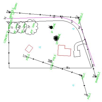
Now the drawing appears as shown below:
NOTE: Within CAD, the desired World Coordinate System (as indicated by the USCICON, if shown at the lower left) is still maintained and coordinate locations for all points and directions of lines have not changed. In other words, only the orientation of the data on the screen has changed!
Select attribute(s) to erase (Enter to end): pick the 3 poles and the 4 iron pins and then press Enter when complete
Twist by [<Twist screen>/Azimuth/Entity segment/Follow polyline]? press Enter for Twist Screen
Attributes to twist [<All>/Symbol/Name/Elevation/Description]? press Enter for All
Enter angle relative to current twist screen<45.0>:? 0 (press Enter)
Select points from screen, group, or by point number [<Screen>/Group/Number]? press Enter for Screen
Select Carlson Software points.
[FILter]/<Select entities>: all (press Enter)
[FILter]/<Select entities>: press Enter
The points then twist back orthogonal to the screen, reading once again from left-to-right.
Select attribute(s) to move: pick an attribute to move
Displacement: pick the new location for the attribute
Rotation: press Enter to keep the existing orientation or pick the new orientation for the attribute
Then the command repeats. Notice how the text "ghosts" as it moves, which helps you place it in the best position. Try to duplicate this result:
Select the text to flip.
[FILter]/<Select entities>: pick the upside down E's individually and then press Enter (see above image)
Click OK when complete. Then click the Annotate -- Survey Text -- Building Dimensions command and pick on the house.
- General tab - Previous Labels: Erase
- Angle tab - Bearing Annotation Precision: Deg, Min, Sec
- Distance tab - Decimals: 0.00
- the fence line
- the polyline containing the arc
- the lower polyline, which is still the western polyline although you have twisted the screen so that it runs along the lower portion of the drawing
NOTE: When you move the lower bearing or distance label (the 404.90' or S 17°05'38" E bearing) to the left, you want to move perfectly level to the screen, since this was the line you used to twist the screen, and it runs perfectly left-to-right. To do this, press the F8 function key to activate Orthogonal (ortho) mode. Then pick the desired piece(s) of text and move it/them to the left, picking the final position. After you move the item(s), press F8 again to turn off Ortho. Sometimes you will load a drawing from another client or source, and the Ortho setting has been left on. This may initially confuse you during the Move commands. Press F8 to deactivate Ortho. Notice that F8 works even with Twist Screen active.
If needed, erase selected portions of the arc annotation via Edit -- Erase -- Select (keyin e). When prompted to Select objects:, simply click the pieces of arc annotation and press Enter when complete:
As needed, use the Annotate -- Annotate Arc -- Label Arc command to better control the placement of the arc annotation. When prompted, select the arc from the screen. The Label Arc Settings dialog box appears:
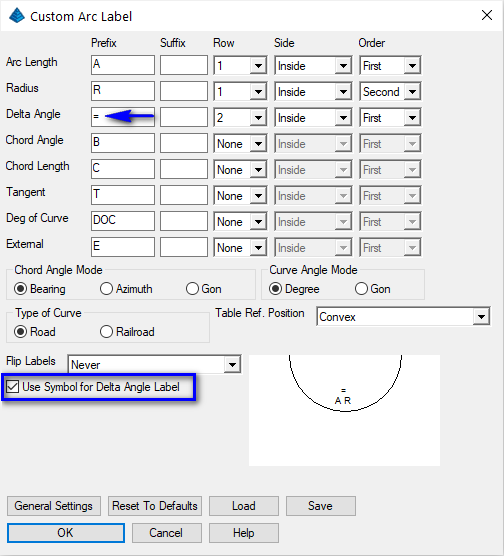
Experiment with:
- locate the Arc Length and Radius inside and closest to the arc and in the order cied, and,
- locating the Delta Angle inside the arc and a bit further from the arc, and,
- replacing the "D" letter with the triangular Greek "Delta" letter as is often commonly practiced.
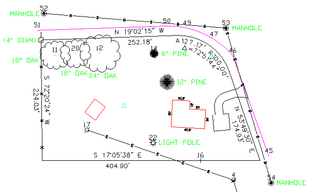
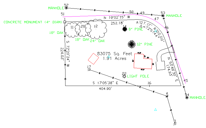
Select the Area/Layout -- Area by Lines & Arcs command. When prompted to Select objects, pick the three polylines that taken together, completely enclose the property.
Pick an area labeling centering point for the area label approximately centered within the parcel as shown below:
- the symbol of Point 16 (the PL point)
- the "hub" symbols (triangles)
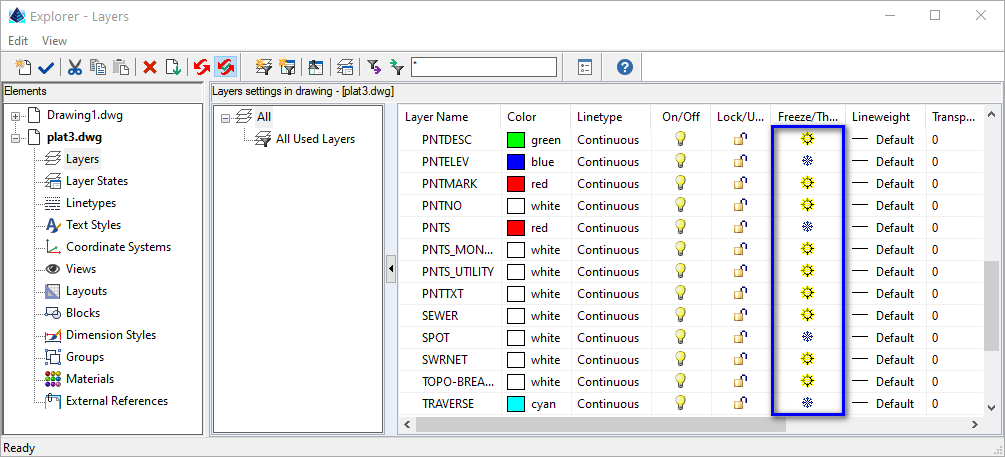
We'll complete the remainder of the cleanup process by manually freezing the PNTNO layer via the View -- Layer Control command. Locate the PNTNO layer and turn the sun icon into a snowflake and close the Layer Control dialog box when complete.
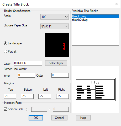
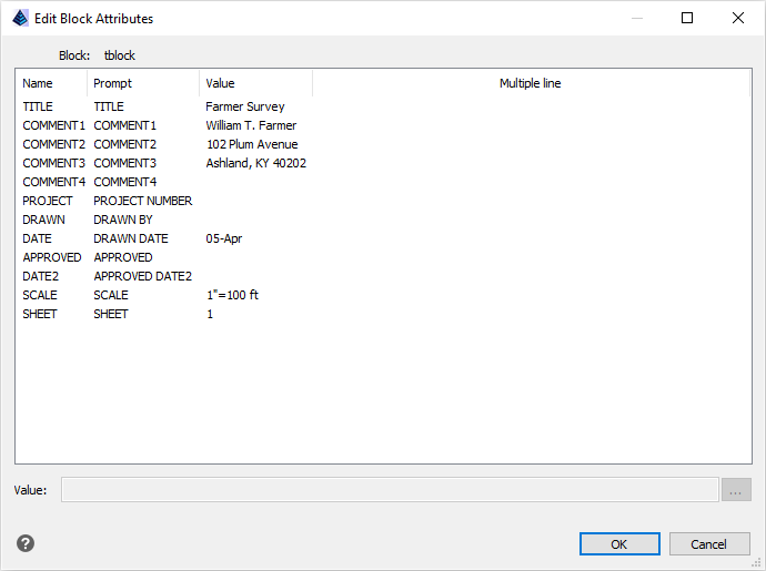
Be sure the items above match your own. Click OK. For the insertion point, select a point at the very lower-left of the screen, so that your drawing plan entities fit inside the border and somewhat nearer to the top. Pick your screen location. You will then be prompted for the attributes of the title block. Fill them in and click OK.
If you prefer, you can use the Edit -- Move (keyin m) command (pick the title block and two border perimeters) to a desired location. Refrain from moving the drawing because you will change the coordinates if you do.
Pick an upper-left location point in the available space to the lower-left of the plat. If you did not save a legend in Lesson 2 (or you skipped Lesson 2), follow the steps in that lesson. As desired, you may use the Points -- Resize Point Attributes command and scale up the oak tree symbol in the Legend by a factor of 1.5.
Use the Annotate -- Survey Text -- Survey Text Defaults command. Change the Offset Dimension Text - Text Alignment to Horizontal and click OK. Then, click the Annotate -- Survey Text -- Offset Dimensions command and pick the lower right corner of the building, and then the lowermost property line (in the current twist screen position). This labels the offset dimension horizontal to the current twist screen.
Click the Annotate -- Draw North Arrow command and find and select the North Arrow symbol that is shown in the figure below. Change the Symbol Size Scaler, if necessary. Click OK. Then pick an appropriate location and press Enter. Note how the arrow draws due North, respecting the twist screen.
Click the Annotate -- Bar Scale command and pick a location near the lower-left portion of the drawing.
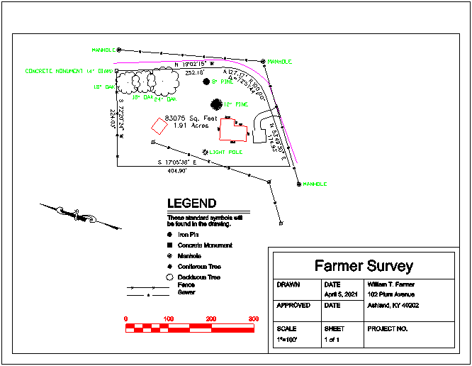
Your drawing should now look similar to this:
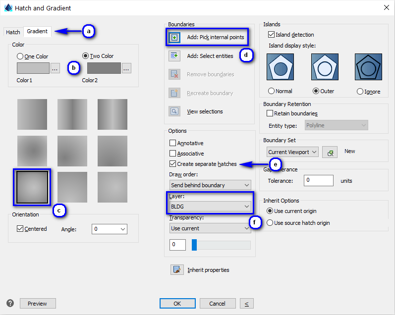
- Select the Gradient tab
- Use the "..." color-picker and choose Index color 9 for Color 1 and Index color 8 for Color 2
- Click the "Radially centered" tile
- Click the Add: Pick internal points and when prompted, pick an internal point in the house and the shed, and press Enter
- Enable the Create separate hatches toggle
- Set the Layer to be BLDG (the same as the house and shed)
- First try using the Edit -- Offset -- Standard Offset command and try offsetting the edge-of-pavement polyline that runs roughly parallel to the sewer line. You will see an error message because that object is a 3D Polyline, created by the Draw Field to Finish command.
- To offset a 3D Polyline, you must use a command specifically
designed to offset 3D Polylines. Use the Edit -- 3D Polyline
Utilities -- Offset
3D Polyline command. Enter the offset method as Interval, press
OK.
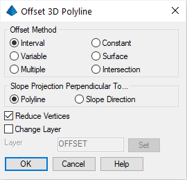
When prompted:
Vertical/<Horizontal offset amount>: 30
Percent/Degree/Ratio/Vertical offset amount <0>: press Enter
Select a polyline to offset: pick the EOP polyline
Select side to offset [Both]: pick out and away from parcel for the other side of the road
Select a polyline to offset (Enter to end): press Enter
Click New, enter TITLE in the New Text Style dialog, and click OK.
Define the TITLE style consisting of the ic-romant.shx font (or romant.shx if using an AutoCAD-based platform) and an Oblique Angle of 10° by entering the settings as show below:
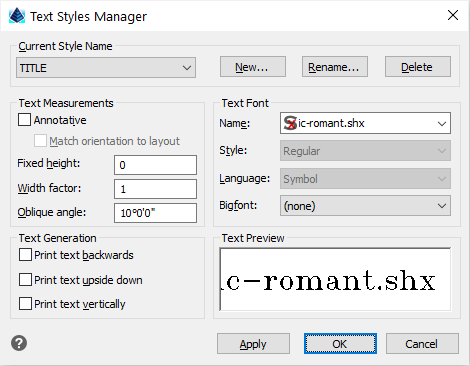
Then click OK. Now, run the DText command by typing dtext at the command line, and place the text at the top of the drawing as follows:
Specify start point of text or [Justify/Style]: J
Enter an option [Left/Center/Right/Align/Middle/Fit/TL/TC/TR/ML/MC/MR/BL/BC/BR]: c
Specify start point of text or [Justify/Style]: pick a point near the top-right of the drawing
Height of text <8.00>: 20
Rotation angle of text <E>: pick a point to right of first point with <Ortho on> (F8), dynamically stretch right
Text: Farmer Survey (press Enter)
Text: April 5, 2021 (press Enter) Text: press Enter
Use the Edit -- Text -- Text Enlarge/Reduce command. When prompted for Scaling Multiplier, enter 0.8 and pick the date you just entered.
Click Draw -- Leader -- Leader with Text command and follow the prompts below:
Options/Size/Pick Arrow Location: nea (we want to use a NEArest snap)
Snap to NEA of: pick near or on the left side of the house
To point: pick off to the left
Next point (Enter to end): press Enter
Text: 2-Story
Text: Farm House
Text: press Enter
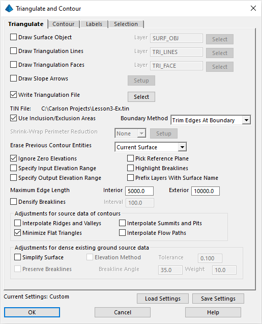
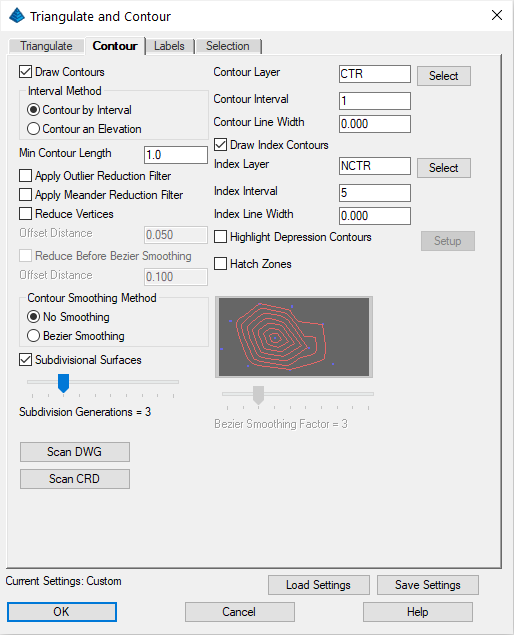
Also make sure to enable the Use Inclusion/Exclusion Areas option. Navigate to the Contour tab and set the values as shown below:
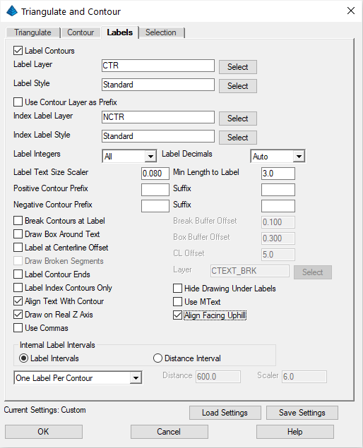
Click on the Labels tab and match the following dialog:
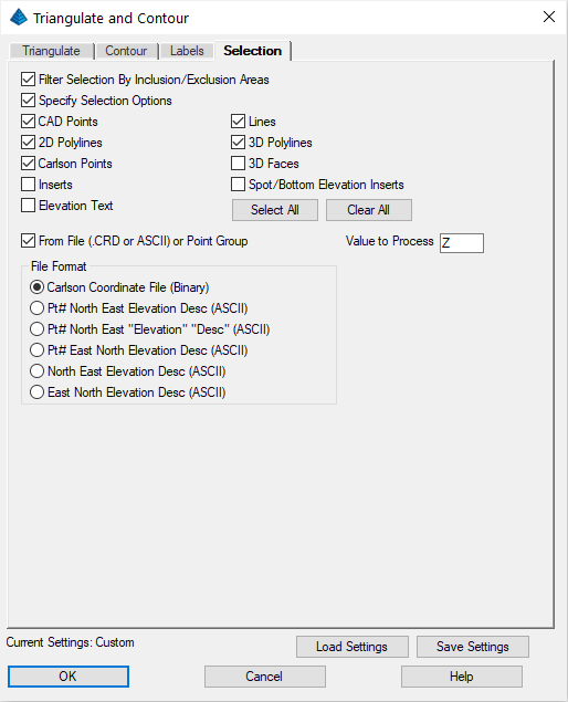
Click on the Selection tab and fill out to match the following:
Press OK and then answer as follows:
Select Inclusion perimeter polylines or ENTER for none.
[FILter]/<Select entities>: press Enter for none.
Select Exclusion perimeter polylines or ENTER for none.
[FILter]/<Select entities>: select the outlines of the building and the shed, and then press Enter
Select points and breaklines to Triangulate.
[FILter]/<Select entities>: press Enter (we're going to fetch the coordinates out of a specified coordinate file)
Select Coordinate File to Read (dialog): plat3.crd (and click Open)
Points to Triangulate (dialog): click OK
The contour map is created. The final drawing will look similar to this: