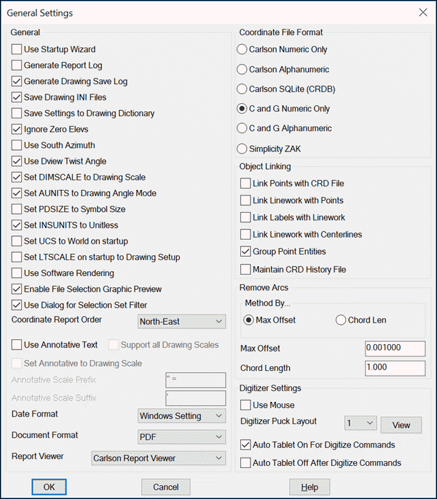
This command allows you to set up the default settings that are used each time you start a new drawing, or load an existing drawing.

NOTE: When using Carlson products with an "embedded AutoCAD OEM engine" (e.g. Carlson Survey with Embedded AutoCAD or Carlson Takeoff with Embedded AutoCAD), only a subset of the various configuration commands will be available.
Load: This command permits a previously saved configuration (CFG) file to be loaded into the software and is useful for propagating corporate standards to groups or individuals within an organization.
SaveAs: This command "packages" up all current configuration settings and permits them to be saved to a named configuration (CFG) file that can be shared with users of Carlson Software.
Use Startup Wizard: When enabled, a dialog-based "wizard" interface is used for the creation of a new project
Generate Report Log: When enabled, output from several commands will be
accumulated in a report buffer. Commands that output to the report
log include Inverse, Traverse, Curve Info, etc. Also, any
report that is displayed in the standard report viewer is also
added to the report log. While activated, the report log resides in
the lower left corner of the desktop as a minimized title bar that
shows how many lines are in the report buffer. To view the report
log, pick on the maximize icon on this title bar. You can also view
the report log by running the Display Report Log function in the
Inquiry menu. The report log can be edited, saved to a file or
printed. To quickly turn the report log on and off, you can type
REPORT at the command prompt.
Generate Drawing Save Log: This
option stores the time stamp and user name in the DWG each time the
drawing is saved. This save log can be viewed using the Drawing
Save Log command.
Save Drawing INI Files: This option stores the file names of data files used with
the current drawing. When enabled, an .INI with the same name as
the DWG file will be created to store the data file names. These
file names are used for the list of recent files when selecting
data files and the Drawing Explorer
command manages the list of these data files.
Save Settings To Drawing Dictionary:
This option saves the settings for commands within the drawing.
Commands always store settings at the program level for recall the
next time the commands are run. By storing settings with the
drawing, each drawing will recall the command settings used in the
drawing. For example, if you run Triangulate & Contour at an
interval of 5 in Drawing_A, then use interval 1 in Drawing_B, then
the next time you contour in Drawing_A it will recall interval 5
instead of using the last interval of 1.
Ignore Zero Elevs: This option will ignore any entities with a zero elevation. It is used for many commands, such as Triangulate and Contour or Make Grid File.
Use South Azimuth: Turning on this option will use a South Azimuth instead of a North Azimuth as the basis for 0 degree.
Use Dview Twist Angle: This option makes the program create text entities at an angle to match the current VIEWTWIST system variable so that the labels are horizontal to the screen twist angle. This twist angle can be set with the DVIEW command or the View > Twist Screen commands. In IntelliCAD, this option also controls the USEVIEWTWIST system variable for making MLEADER and MTEXT default rotation to be horizontal to the current screen twist angle.
Set DIMSCALE to Drawing Scale: This will set the dimension scale to match the drawing scale.
Set AUNITS to Drawing Angle Mode: This will set the DWG angular units to match the angle mode established under Drawing Setup.
Set PDSIZE to Symbol Size: This will set the PDSIZE scale to match the symbol size defined in Drawing Setup.
Set INSUNITS to Unitless: This will set the INSUNITS (Insertion Units) CAD system variable to Unitless (INSUNITS=0) when the drawing is opened.
Set MENUBAR on Startup: When enabled, the Carlson Menu associated with the Carlson icon (usually on the PC Desktop) will be loaded. Otherwise, use the Carlson Menus command to select the desired menu.
Set UCS to World on Startup: When enabled, drawings with a User Coordinate System (UCS) other than World will have the UCS set to World.
Set LTSCALE on Startup to Drawing Setup: When enabled, the linetype scale (LTSCALE) variable will be set to the Horizontal Scale defined under Drawing Setup.
Use Software Rendering: When enabled, commands that use OpenGL functionality (such as 3D Viewer Window) on computers with older video cards that don't offer extensive hardware acceleration will attempt to render the information with any available random-access memory (RAM).
Use Dialog For Selection Set Filter: For IntelliCAD, this option chooses whether to prompt for selection set filters in a dialog or command prompt at the "Select objects" prompt.Use Annotative Scale: When enabled, text created by Carlson routines such as Annotation will use scale-able annotative properties. This setting also applies to symbols created by Draw > Insert Symbols. Carlson Points have a separate setting for annotative under the Point Defaults command.
Support All Drawing Scales: When enabled, text placed as annotative entities will make use of all annotation scales currently defined within the drawing.
Set Annotative to Drawing Scale: This option sets the annotative scale to match the Horizontal Scale set in the Drawing Setup command.
Annotative Scale Prefix/Suffix:
These strings are used for naming annotative scales when the
program creates new annotative scales. For example, when the
program creates an annotative scale for a horizontal scale of 50,
you can name the annotative scale as 1:50 or 1"=50' depending on
these string settings.
Coordinate Report Order: You can choose the traditional North-East format, or reverse these in reports with an East-North format.
Date Format: You can control the display of dates in Carlson reports with this drop-down menu. The default is "Windows Setting" which allows you to control it with Windows Control Panel. Several other common formats are available.
Formatted Document Type: (AutoCAD-based platforms, only) Use this option (for commands such as 3D Viewer Window to establish the type of document produced by the command.
Report Viewer: This option chooses between the Carlson Report Viewer,
Windows Notepad and Microsoft Word for the viewer to use for
reports that the Carlson commands generate.
Dialog Font: This option chooses
which Windows font to use for Carlson dialogs.
AutoCAD Menu: (AutoCAD-based platforms, only) This option chooses which AutoCAD menu to load when picking the AutoCAD menu from the Carlson Menus toolbar or from the Settings > Carlson Menus pull-down menu. When AutoCAD Map is installed, there are different layouts of the Map menu to choose from. When Autodesk LandDesktop is installed, those menus are available.
Object Linking: The Object Linking section contains options for creating additional "intelligence" on Carlson-placed entities:
Coordinate File Format: Carlson can be configured to utilize a variety of coordinate file formats:
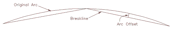
Remove Arcs: Since 3D polylines do not allow true arcs, the program represents arcs in 3D polylines as a series of short chords. The Remove Arcs settings control the spacing of these arcs:
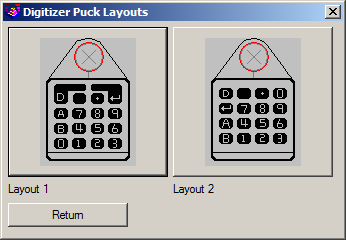
Digitizer Puck Layout & View: There are two main formats for the digitizer puck. They are numbered 1 and 2. Selecting the View button brings up the window showing the two formats.
Use Mouse: This option allows you to use the mouse instead of the digitizer puck for the digitize commands.
Auto Tablet On for Digitize Commands: This option will activate the tablet when using the digitize commands.
Auto Tablet Off for Digitize Commands: This option will de-activate the tablet when using the digitize commands.
The settings under Drawing Setup are used to establish
the initial values when creating a new drawing. Most of these
settings are identical to those discussed in Drawing Setup. There are a
few additional settings. The Vertical Scale is used by
profile and cross section routines for the grid scale. The Point
Prompt-Label Settings, Point Number Settings and Vertical Angle
Mode settings are described in the Points > Point Defaults
command. The Drawing Setup Source on Startup control the source
for the initial settings for a new drawing. The Use
Configuration option uses the settings from this dialog. The
Use Drawing Template uses the settings stored in the drawing
template (dwt). To store settings to the dwt, open the dwt and run
the Drawing Setup command and then save the dwt. The settings are
then automatically stored in the dwt.

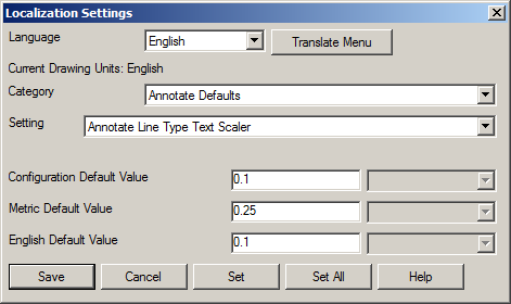
There is also the ability to maintain two different sets of defaults (English and Metric). You can maintain a separate set of settings for each unit system, especially if you switch back and forth. Also added was support for meters/metres, tons/tonnes and various date representation which can be accessed via the Localization Settings button.
Please refer to the Set Project/Data Folder command for complete information.
These options are used for starting Carlson. Defaults are set here, and will be used at the beginning of each session.
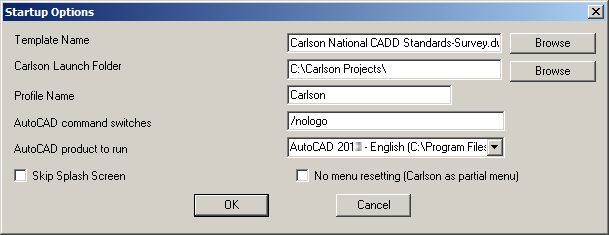
Template Name: This is the drawing template file that will be used when starting a new drawing. The Browse button allows for selecting a new file.
Carlson Launch Folder: This is the folder where Carlson projects would be stored by default. The Browse button allows for selecting a new folder location.
Profile Name: This is the AutoCAD/IntelliCAD Profile that will be used when working in Carlson. If you use a custom profile, be sure that the profile contains the Carlson support folder in the Support File Search path (ie. %appdata%\Carlson Software\Carlson version\CAD version\SUP), and the Carlson main menu must be loaded. If the custom profile doesn't have these requirements, then the program switches to the default Carlson profile.
AutoCAD command switches: This turns off the AutoCAD "splash" screen upon launching the program. The /nologo takes the splash screen out of the start-up procedure. See AutoCAD documentation for other switches that are available for use.
AutoCAD product to run: (AutoCAD Only) This is the AutoCAD version and flavor (Map or LDT, etc.) that Carlson is installed for, and will run with.
No menu resetting: (AutoCAD Only) This controls whether to set the Carlson menu as the main customization file on startup or to keep the current main customization unchanged.
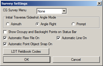
CG Survey Menu: Indicate whether to add-on the C&G Survey pull-down menus to the standard Carlson Survey menus. The Compact mode has all the C&G commands in a single pull-down menu. The Expanded mode has all eight C&G pull-down menus that C&G "stand-alone" used to have.
Initial Traverse/Sideshot Angle Mode: This sets the default angle mode for these COGO commands.
Show Occupy and Backsight Points on Status Bar: This is an option for the COGO Inverse command.
Automatic Raw File On: This is equivalent to toggling on the COGO > Raw File On/Off automatically when the drawing is opened.
Automatic Line On: This is equivalent to toggling on the COGO > Line On/Off automatically when the drawing is opened.
Automatic Point Object Snap On:
This is equivalent to toggling on the Settings
> Point
Object Snap On/Off automatically when the drawing is
opened.
Automatic Compare DWG points with
Coordinate File on Startup: This option
runs the Coordinate File Utilities > Compare Points routine when
the DWG file is opened to report any differences between the point
entities in the drawing and point coordinates in the coordinate
file.

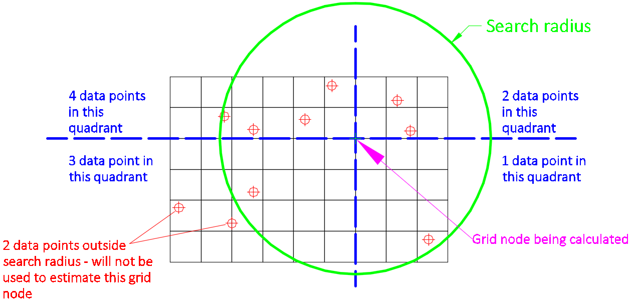
Inverse Distance/LeastSquares Modeling Parameters: The modeling methods of Inverse Distance and Least Squares are similar ways to create a grid from datapoints or drillholes. It is not recommended to use these methods for gridding contour or breaklines. Triangulation is better for that. These methods need a search radius defined. Anything past this distance from one data point to the next will be ignored for influence. The Max Samples are the number of data points that will be used to influence each data point. The area is broken into 4 quadrants. The Min and Max Quadrant are the numbers of data points that will be used in each quadrant.
Specify Grid Resolution As: There are two ways to create a grid file. Once the boundary has been selected, the cells need to be determined. Number of Cells in X and Y will divide the boundary up into the specified number of cells. These will then be odd shaped rectangles, with the size calculated by the boundary dimensions and the number of cells. The Dimensions of Cells is the more commonly used method. This will allow for a set cell size for the X and Y directions. Most of the time the grid cells should be square, where you set the size.
Grid Precision: This is the number of decimals that are stored in the grid file.
Draw Contours Max Number of Rechecks for
Crossings: Routines that generate
contours check for any crossings that can occur from smoothing or
reduction options. When a crossing is found, the smoothing or
reduction factors are reduced and then the contours are rechecked
in case that adjustment causes a new crossing. This option can be
used to decrease the number of rechecks in case your dataset is
large and you don't want to take the time for these
checks.
Save Grids Using Binary Format: This
options chooses between saving .grd files as either text or binary
files. This setting applies to all routines that save grid files.
The advantage of the text format is the ability to view the grids
using any text editor like Notepad and the ability for non-Carlson
programs to easily read the grids. The advantage of the binary
format is the speed of saving and loading the grids which is
several times faster than the text format. Only Carlson 2015 and
later versions can read the binary format. When the range of
min/max grid values is small enough relative to the grid precision, the
program will automatically switch to an indexed binary format which
uses half the file size and loads twice as fast.
Simplify Difference TIN to Reduce
Size: When difference TIN is calculated, the intersection of
individual triangles is calculated. When two source TINs are large
and somewhat similar, the resultant TIN can have exceedingly large
number of triangles. This option seeks to limit the growth of
intersection TIN by keeping the points on the breaklines and in the
areas major surface changes (based on the normals) while
eliminating extraneous points in flat areas. While this results in
some approximation of the difference TIN, the resulting surface has
significantly fewer points and minor slivers.
Track TIN History: When this option
is enabled, the information about creation of the TIN and editing
operations is stored in the TIN. This allows to review the history,
modify the steps and rebuild the TIN in Surface Manager ->
History utility.
Include Detailed Source Data: When
TIN history is enabled, this option adds additional data about
entity data, allowing user to recreate the surface without original
drawing or when the source entity is no longer in the drawing.
Without this option, only handles (IDs) of entities are
stored.
Track Surface Data Changes: When the
TIN is made and added as a surface to the Surface Manager, the
source selection set used to create the TIN is stored in the
drawing. When this option is enabled, the changes to the source
entities will be tracked and TIN will be updated accordingly,
recreated with same options as originally.
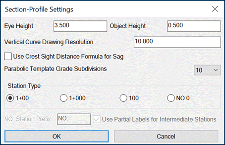
Eye Height and Object Height are used for
calculating sight distance on vertical curves.
Vertical Curve Drawing Resolution applies to Draw Profile
for the segment length for drawing vertical curves.
Use Crest Sight Distance Formula for Sag:When this option is
on, the Crest Vertical Curve formula is used to calculate the sight
distance for sag vertical curves. Otherwise the the Sag Vertical
Curve formula is used.
Parabolic Template Grade Subdivisions applies to Process
Road Design and Road Network for how many 3D polylines to draw for
grades defined as parabolic in the template.
Station Type controls the format of station labels. For the
NO.0 type, there is a setting for the label prefix, and the Use
Partial Labels for Intermediate Stations option will skip the label
prefix for odd stations.
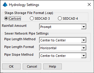
Stage-Storage File Format:
Indicate the format of the Stage-Storage File
to be used in Carlson Hydrology. Carlson method should be used as default. SEDCAD 3 and 4
is a comprehensive hydrology and sedimentology package by others
that Carlson can output data files to be used.
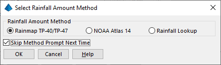
Rainfall Amount Method: Rainmap
TP-40/TP-47, NOAA Atlas 14 and Rainfall Lookup methods are
available. The program defaults to the Prompt option and the
rainfall amount program will show all three methods when Prompt is
on. When users select a method and check the "Skip Method Prompt
Next Time", the method is set to the default rainfall amount
method.
Rainmap TP-40/TP-47: Get the
rainfall amount on the rainfall map.
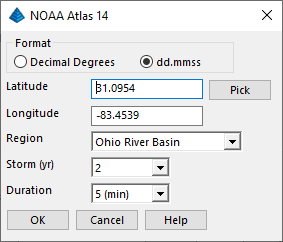
NOAA Atlas 14: Rainfall amount
is download automatically from NOAA website by specifying the
location.
Rainfall Lookup: This is a
rainfall lookup table created by users. It can be accessed for all
the hydrology functions to get the rainfall amount.
Sewer Network Pipe
Settings: Specify the pipe settings based on
jurisdictional requirements.
Pipe Length Method can be set for Center to
Center or Actual Pipe Length.
Pipe Length Format can be set to Horizontal or
Slope Length.
Pipe Slope Format
can be Center to Center or Actual Pipe Length.


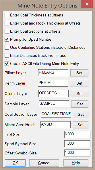
These options will toggle various prompts when entering Mine
Notes in the Underground Mining module. You can also set the layers
for various linework needed for geologic modeling and mine
planning. These options are further described in the documentation
of the the
Mine Note Defaults command.
This is the configuration screen for default settings used with the Mining Modules. Each item is detailed below.

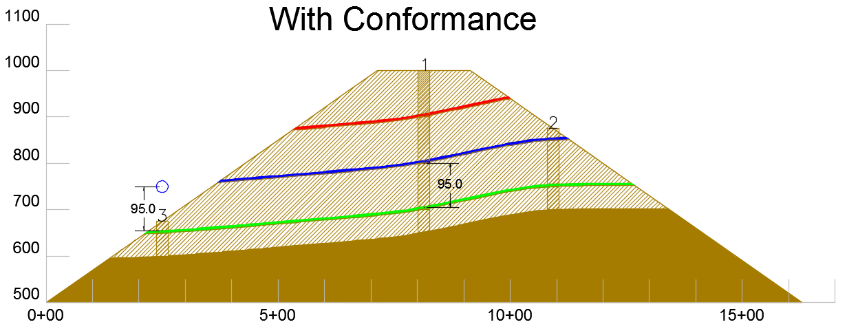
Fill in Missing Strata Above/Below Existing
Strata (Seam Stacking/Conformance): This option determines how the program handles drillholes
with missing strata. An example of a data set modeled with and
without the conformance option is shown below. Notice that when
conformance is applied, the red and blue strata will more closely
mimic the green strata, even though the red and blue strata do not
occur in all three drillholes. The program does this by
artificially adding data points to the drillhole with missing
strata.
In the below example, consider drillhole #3. This drillhole does not contain the blue strata. To make the blue strata conform to the green strata, the program will search for the nearest drillhole that contains the blue strata (in this case, Drillhole #1). The program will then measure the elevation difference between the blue and green strata and apply that same elevation difference in drillhole #3. In this example, the bottom of the blue strata and the top of the green strata in Drillhole #1 are 800' and 705', respectively (a difference of 95'). The top elevation of the green strata in Drillhole #3 is 655'. So, when the program models the blue strata, an artificial elevation of 750' (that is, 655' + 95') will be used in Drillhole #3. In this case, the green strata is considered to be the "marker" and the blue strata is considered to be the "target".
In drillhole #2, the red strata is not present. In this case, either the blue or the green strata could serve as the "marker" strata. When the "All" option is used, the program will automatically select one of these strata to be the "marker". The program will set the "marker" strata as the strata closest to the "target" strata. In this example, the red strata is closer to the blue strata, so the blue strata will be used as the "marker". If the "Seam-Specific" option is used, you will have to manually define which strata are "markers" and which strata are "targets".
Although this example shows the result of seam stacking/conformance applied to an area with sufficient drilling depth in an area with varying topography, the same effect can be applied to drillholes that are not simply drilled deep enough to intersect all strata.

None: This option will not apply seam stacking/conformance. In this scenario, each strata layer will be modeled independently of other strata layers. Only strata data that is actually included in the drillhole will be used to make the strata grid file.
All: This option will apply conformance in any way possible. This can be a useful option when the structure of all strata are similar. However this option does not give you the option to specify which strata layers are "markers" and which strata are "targets".
Seam Specific: This option also applies conformance, but requires that you specify which strata are "markers" and which strata are "targets". The strata are tagged as "markers" and "targets" in the Define Strata/Bed command. It is important to note that when using this option, you can define the "Marker Level", which sets the priority of the marker strata (this is an optional field, but it can have a significant impact on the model when multiple marker strata are available for use).
Use Conformance for Channel Samples: This option controls whether to use channel samples as source data points for conformance of other strata.
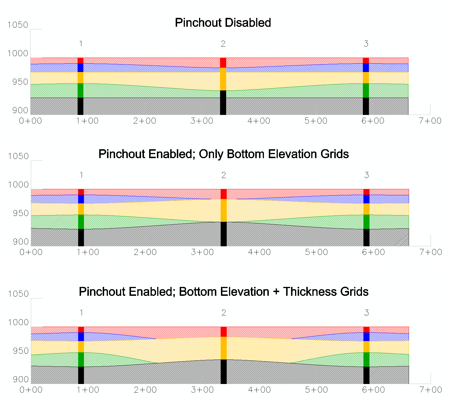
Calculate Strata Pinchout: This option determines if the
thickness of a seam is pinched out when it does not occur in a
drillhole, as shown in the below image.
When pinchout is disabled, as shown in the first cross section in the above image, the middle drillhole is completely ignored when making the grids for the blue and green strata. This results in the blue and green strata suggesting a significant thickness at the location of drillhole 2. In the second cross section, pinchout has been enabled, but the results are misleading becasue no thickness grids were incorporated into the model. In the third cross section, pinchout has been enabled and the thickness grids have been incorporated into the model to accurately model the pinchout.
It is important to note that elevation grids will not be automatically modified to show the pinchout, although the elevation grids may in fact be adjusted somewhat. It is therefore recommended to only enable this option when making thickness grids to avoid misleading results. When the program creates a thickness grid with this option enabled, the missing strata will be modeled as having a negative thickness at the drillhole without the strata. The thickness value will be equal but opposite to the thickness of the nearest thickness data point for that strata. In the above example, the blue strata has a thickness of 10' in drillhole 1, so the program will use a value of -10' in drillhole 2 when making the blue thickness grid. By incorporating a negative thickness value, the thickness will approach a value of zero approximately halfway between the drillholes 1 and 2. The Pinchout Slider bar to the right of this toggle in the dialog controls where the strata will actually pinchout. Before the thickness grid is written, it will be modified so that all negative values are reset to zero. This results in a thickness grid that begins to decrease in value as it nears the drillhole with the missing strata, but never shows a negative thickness.
Since this option is only intended to be used when making thickness grids, you will need to create modified elevation grids before adding them to the Geologic Model. This can be done quite easily with Grid File Utilities. In the above image, notice that the blue and green strata layers only pinch out properly when the elevation grids have been modified. In this case, the top of the blue strata was created by adding the bottom elevation grid of the blue strata to the thickness grid of the blue strata. Notice that in the second diagram in which only bottom elevation grids were used, the blue strata does not pinchout between the drillholes.
Finally, it is important to note that pinchout will only affect thickness grids when two "sandwiching" strata are detected above and below the missing strata. In the above image, the blue strata is "sandwiched" between the red and yellow strata. If drillhole 2 did not contain the red strata, then the blue strata would not pinchout. This means that the top and bottom strata in any given model will not be able to pinchout.
Pinchout Zero Thickness:
This option determines if a strata with a
thickness of zero will be modeled as a pinchout. Pinchout is
normally only applied for strata layers that are absent in a
hole.
Pinchout Key Only: This option will only apply the pinchout to the Key strata
while the Non-Key strata will be modeled as if the pinchout were
not applied.
Adjust Non-Key for Estimated Key
Strata: This setting controls whether to adjust non-key strata
to fit in key strata for pinchout or conformance.
Restrict Pinchout to Drillhole Elevation Range: This option controls where the seam will pinchout. If there is a shallow hole, and a seam is running beneath it, this setting will pinchout the seam if it is off. If it is on, then the seams will only pinchout if they pass through the elevation range of the drillhole. This is useful if it is desired to pinch out a seam that passes above or below the elevation range of the drillholes. For most applications, it is recommended to leave this option disabled.
Include Strata Name in Bed Composite: This option will add the strata name to the bed name when running the bed compositing commands, such as Split Bed by Parameters.
Composite Bed Qualities by Density:
When creating grids of bed qualities from
drillholes with multiple samples of the bed quality, the quality
will be composited to a single data point before the grid file is
made. By default, the quality will be averaged by the thickness of
the sample. When this option is enabled, the qualities will instead
be averaged by weight (thickness * density). The Density
Attribute Name sets the name of the density attribute to be
used for weighting. Density is always expressed as lbs/ft^3 or
kg/m^3.
Use Strata Limit Lines: This option determines if
Strata Limit Polylines will be used for modeling. If this
option is disabled, you will not be prompted to select Strata Limit
Lines when modeling.
Auto Select All Strata Limit Lines:
This option will automatically select all
Strata Limit Polylines when modeling. You will not be prompted to
select the lines when this option is enabled.
Process Only Strata with Beds:
This option will ignore all strata layers
without a bed name when modeling. This can be useful when
overburden/interburden layers are not marked with unique strata
names and have not been tagged with a bed name.
Process Only Strata with Definition:
This option will ignore all strata that are
not listed in the current Strata
Definition file when modeling. However, strata layers that are
not included in the Strata Definition file will still be used to
calculate conformance and pinchout.
Dip Angle Direction: This option
determines how drillhole dip values are interpreted. The default
option of 0 = Down| 90 = Horizontal| 180 = Up will
treat dip values of 0 degrees as vertical in the downward
direction, dip values of 90 degrees in the horizontal plane, and
dip values of 180 degrees as vertical in the upward direction. The
other options may be used to accommodate other dip value schemes.
Dip Angle Method: The Direct method
simply applies the dip angle of the sample to the depth of the
sample. The Minimum Curvature method looks at two adjacent samples
at a time and calculates assuming the samples lie on a circular
arc. The Min Curvature From Bottom method considers the sample
point to be at the bottom of the sample and pairs this point with
the dip from the previous sample. The Min Curvature From Top method
considers the sample points to be at the top of the sample and
pairs this point with the dip from the next sample.
Store Source Data in Grids: This option will include the source data used to make strata grid files within the grid itself. This includes the X-Y coordinates of the data point, the value used for modeling, and the type of data source (drillhole, channel sample, etc.). This can be useful for understanding how the grid file was generated when the original source data is not available.
StrataCalc Drillhole Selection
Method: This option determines how the
program will prompt for geologic data when modeling. The
On-Screen Drillholes option will prompt you to select
drillholes, channel samples, etc. when making the geologic model.
The StrataCalc File option will instead prompt you for a
.stc file, which can be saved from the
StrataCalc Data Sheet command. The .stc file can be useful when
you need to be certain that the same information is being used to
create model between iterations.
Stripping Ratio Units: This option
sets the units to be used when reporting Stripping Ratio. Some
commands, however, will not respect this option, and will instead
report Stripping Ratio using the default units of (yd^3 waste))(ton
key) or (m^3 waste)/(tonne key). Commands that are hard-wired to
use the default stripping ratio units are Dragline
Pits,
Vertical Pit Quantities, and
Pit Scheduler. Also, when using
Surface Mine Reserves, when the "Type of Strip Ratio
Contours/Grid" is set to Accumulative, only the default stripping
ratio units will be used for the contour/grid output (be cautious
not to confuse the contour/grid output option with the Accumulative
Stripping Ratio that is included in the report - all stripping
ratio values in the Surface Mine Reserves report will
respect the stripping ratio units selected in Carlson
Configure).
Use 0 Values for Blank Entries in Coal Sections: This option will replace treat blank values in coal sections as 0 rather than considering it to be null.
Draw Coal Sections Z at Thickness: This option will draw coal section symbols at the Z value of the actual thickness. For example, a coal section with a thickness of 5 feet will be drawn at an elevation of 5. This is useful for contouring or gridding the coal sections with standard commands from the Civil module.
Prompt for Advancement Pline for Quantities: This option will prompt you to select an additional advancement polyline when running the Quantities by Average / Grid / Centerline commands. This polyline represents the direction of mining in a particular area. The length of the polyline will be included in the quantity report.
Report Format for Quantities by Avg/Grid Methods: This option determines the default report format for the Quantities by Average / Grid / Centerline commands. However, each of these commands will also let you set the report format when the command is executed. The Standard option will use a simple text editor for the report. The Columns option will still use a standard text editor, but with the values aligned into columns. The Formatter option will send the report to the Report Formatter for user-defined formats.
General Settings:
Key Material Name: This is the name of the Key material you are mining. This name will be used in several reports to identify Key material, such as the outputs from Surface Mine Reserves and Surface Production Timing. If you have more than one type of key material, you may want to give this a more generic name such as "Key Material" to avoid confusion in the reports.
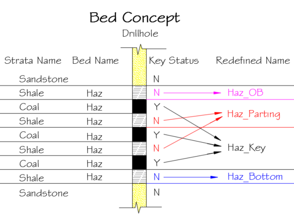
Bed Name Suffixes: KEY, OB, PARTING, BOTTOM: These suffixes are used to identify the four portions of a bed. An example is shown in the below image. When Bed names are applied to a group of strata layers, all strata layers with matching bed names are treated as a single group. This allows the program to properly correlate groups between drillholes even when the number of samples for each bed is not consistent between drillholes. Although the strata will be treated as one group, there are four portions of the bed available for modeling. Note that not all four portions of the bed may not be present in a data set.
OB: This is the non-key portion of the bed above the first occurrence of Key strata.
Parting: This is the Non-Key portion of the bed bound between Key strata.
Key: This is the Key portion of the bed.
Bottom: This is the non-key portion of the bed below the last occurrence of Key strata.
SDPS Directory: This field sets the installation directory for the Subsidence Deformation Prediction System (SDPS) program. The SDPS commands are found under the Subsidence Pulldown Menu of the Underground Mining Module.
Use Map Object Data as Properties: This option will use the AutoCAD Map data to set the Property and Owner names for reserve estimates. When this option is disabled, the program will use the Owner and Property names assigned to polylines from the Assign Property Names command.
These options are used for the Construction module and SiteNet commands in the Civil module.
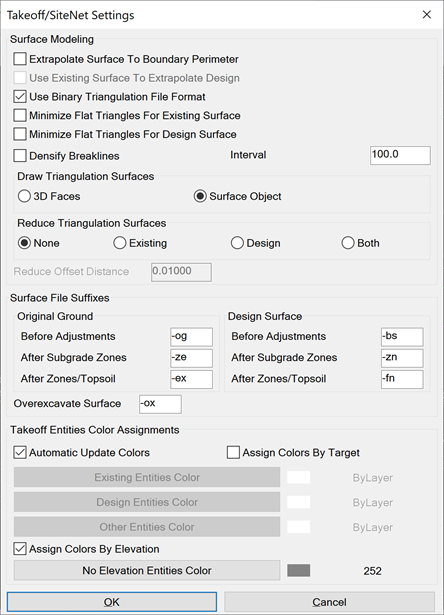
Extrapolate Surface To Boundary Perimeter: When this is check ON surfaces are extended and volumes are calculated out to your boundary perimeter. When this is checked OFF surfaces and calculations end at the extents of your design data.
Use Existing Surface To Extrapolate Design: When this is checked ON surfaces and volumes are calculated to the extents of your existing data.
Use Binary Triangulation File Format: This option sets the format for the surface model files as either binary or ASCII. The binary format has a .tin file name extension and loads about twice as fast and has about 50% less file size than ASCII. The ASCII format has a .flt extension and is the legacy format used by other Carlson products and Softdesk.
Minimize Flat Triangles:
This option reduces the occurrence of "flat"
(or more precisely, horizontal) triangles. Flat triangles often
occur when creating surface models from contour data. The Minimize
Flat Triangle option will swap triangulation edges when possible to
switch flat triangles to sloped triangles.
Densify Breaklines: This option
automatically add vertices on breakline segments for triangulation
at the specified Interval.
Draw Triangulation Surfaces: This
option sets how the Takeoff surfaces are drawn in the drawing. The
3D Faces option creates 3D Face entities for each triangle in the
surface. The Surface Object option creates a single Carlson Surface
Object for the surface which is more efficient on memory and
drawing size.
Reduce Triangulation Surfaces: This causes edges within the selected surface TIN mesh to be collapsed to reduce the number of triangles, edges, and points within the mesh while having a minimal impact on the overall shape of the mesh.
Reduce Offset Distance: This setting is used by the Reduce Triangulation Surfaces command to set the reduction tolerance. Specify the maximum average distance that any point can be moved outside of the plane of any triangle that connects to that point. Values might range from .01 to .1 for most purposes.
Surface File Suffixes: These settings allow you to change the file names for the surfaces generated by the program:
Automatic Update Colors: This refreshes colors in your drawing as they change (i.e. elevating entities, setting layers for different Targets, etc). If your drawing is very large and is slow to automatically refresh you may want to toggle this off and use the Update Colors For Set Elevations command under View when you want/need to see the color changes.
Assign Colors By Target: This option allows you to set the Existing, Design, and Other layers to any color you define.
Assign Colors By Elevation: This option allows you to set the color for entities needing elevations.
No Elevation Entities Color: Indicate the color entities with no elevation (Z=0) should be assigned to when their layer is classified as "Original" or "Design".
There are literally hundreds of default settings that can be set with this dialog. The categories that can be selected from are:
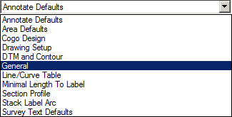
The Settings for each Category will display all of the items that can be setup for default values. The Default value is set in the Configuration Default Value box. The corresponding Metric or English default values are set here, allowing for easy switching between the two systems.
Pulldown Menu Location(s): Settings
Keyboard Command: config_scad
Prerequisite: None
| Converted from CHM to HTML with chm2web Standard 2.85 (unicode) |