CAD Basics
Carlson Software's office products utilize either an AutoCAD or
IntelliCAD-based CAD engine. This section will review some basics
of CAD software that will be useful in running Carlson Software.
Running Carlson on IntelliCAD is largely the same as running on
AutoCAD.
Starting Carlson
Once installed to your computer, one or more Carlson start-up
icons (based on the product[s] contained within the product serial
number) will typically be placed on your computer desktop. Carlson
recommends launching the software through the desktop icon so
proper software initialization parameters can be set. Once the
Carlson software environment has been initialized, you can choose
to open an existing document type (e.g. an existing *.DWG
file) or create a new document type (e.g. a new *.DWG
file). Based on your desired (or established) interface settings,
one of three "start-up" environments may be presented:
- Start Page (IntelliCAD users) -
When this environment is active (i.e. variable STARTMODE =
On), a generic "Start Page" will be displayed with common
first-time commands and the software will wait for your to
generally create a New Drawing or Open Files that the CAD
application supports:
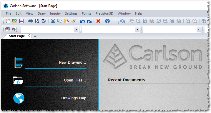
- Clicking New Drawing will launch the Startup Wizard which provides a step-by-step
process for the creation of a new, supported document type.
- Clicking Open Files will launch a File
Selector which permits navigation to a desired folder location on
your computer (and/or shared network drive, if available) which
provides the ability to directly open an existing, supported
document type.
A primary benefit of the Start Page environment is
that only the drawing(s)/documents that you choose to create or
open will be in use by the application. In this fashion, when
exiting from the software, you'll have the benefit of only having
to save changes to documents that are open and that have
changed.
NOTE: The complement of commands offered by the
Carlson module(s) will not be fully loaded until at least one
supported drawing document type is either created or opened.
NOTE: The "Start Page" environment can be
suppressed by enabling the Skip Start Page Next
Time toggle in the lower left corner of the "Start Page."
Enabling this feature will (by default) revert to the Startup Wizard interface the next time the
application is restarted. The "Start Page" environment can be
re-enabled by:
- Opening an existing drawing document, and,
- Keying-in STARTMODE into the Command: prompt, and,
- Setting the value of the variable to On.
- Startup Wizard - When this
environment is active, CAD will launch with a default drawing
document (e.g. Drawing1.dwg) pre-loaded along with an
interface with a step-by-step (aka wizard) approach for
the creation of a new drawing document type:
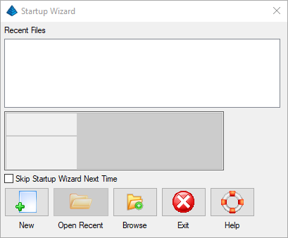
- Clicking Browse will launch a File
Selector which permits navigation to a desired folder location on
your computer (and/or shared network drive, if available) which
provides the ability to directly open an existing, supported
document type.
- Clicking Open Recent will open the
currently selected/highlighted drawing document which has been
previously opened by the application.
- Clicking Exit will dismiss the
Startup Wizard dialog box and leave the default drawing document
active and available for data entry.
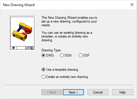
- Clicking New will start the formal
Startup Wizard process which generally entails the following
sequence:
- Establish the desired document type (and/or
source) and click Next >:
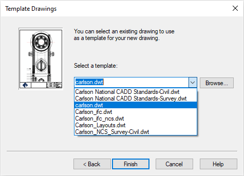
- Establish the source document type (aka
"template") and click Finish to launch into the
drawing-specific settings:
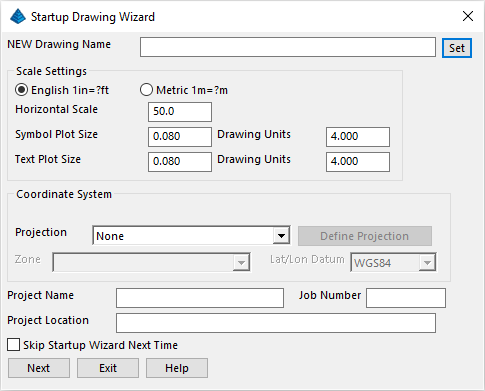
- Establish the document name (e.g. use the
Set button to establish the desired Folder and
Document name) along with expected plot scale and desired
Coordinate System information as desired and click
Next to continue with additional
information:
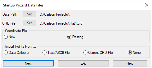
- Validate the Destination Folder and establish the
related "Coordinate File" name to house designated point data and
whether an existing Coordinate File (e.g. such as that
created by Carlson SurvPC
or SurvCE) or if a new Coordinate File should be created along
with the source for any inbound Point Data and click
Next to continue with further processing
instructions (if applicable):
NOTE: The precise sequence of steps within the
Startup Wizard will vary based on the option(s) selected within
each step of the Wizard. It is recommended that the Wizard be
followed to its logical conclusion and the click of a resulting
Finish button.
NOTE: The "Startup Wizard" environment can be
suppressed by enabling the Skip Startup Wizard Next
Time toggle in the lower left corner of the opening "Startup Wizard" dialog box or the
tertiary Document Name dialog box. Enabling
this feature will (by default) revert to the standard CAD interface the next time the
application is restarted. The "Startup Wizard" environment can be
re-enabled by:
- Opening an existing drawing document, and,
- From the Settings menu, click Carlson
Configure, and,
- Clicking the General
Settings and enabling the Use Startup Wizard
option.
- Standard CAD - When this
environment is active, the CAD application starts with a default
document name (e.g. Drawing1.dwg) pre-loaded and ready for
data entry. It is up to the user to properly save and rename the
drawing document to a desired folder and file name.
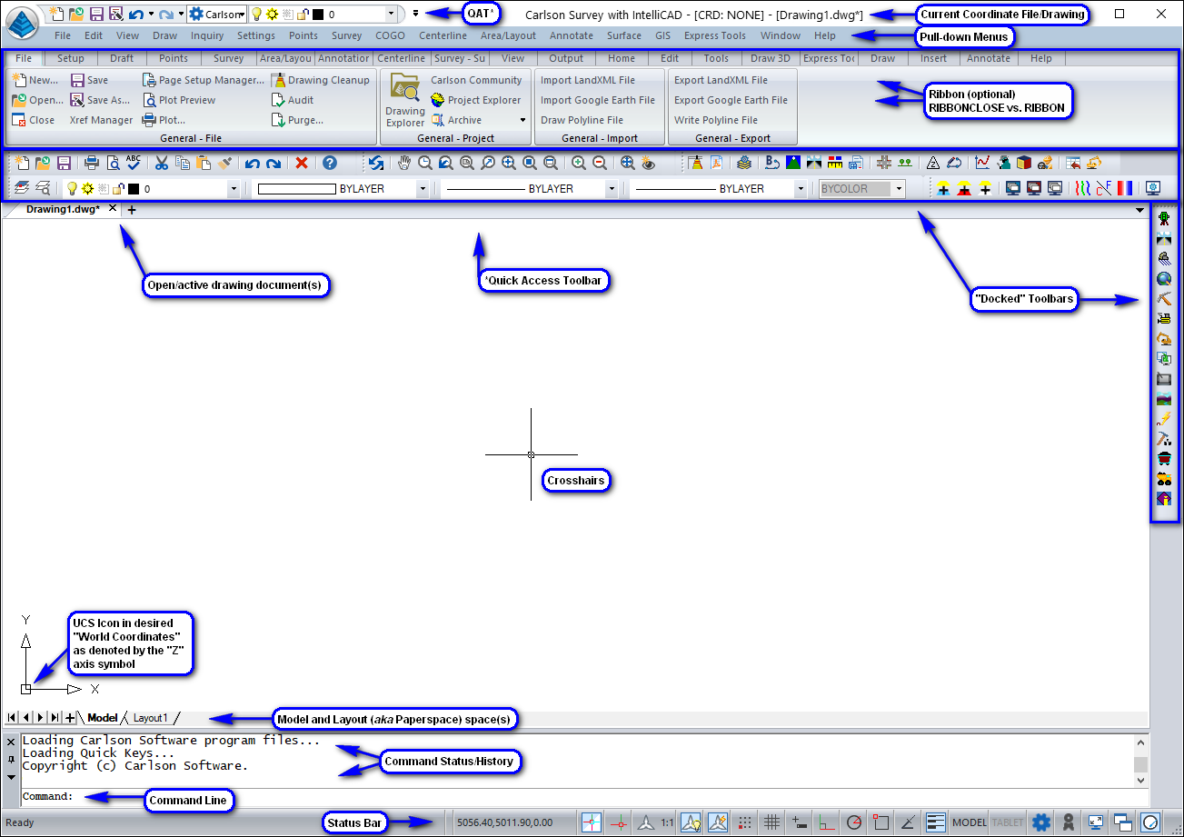
CAD "GUI" (Graphical User Interface) Overview
When configuring the "GUI" (gooey) interface and/or effectively
communicating with Carlson Technical Support, it is helpful to
understand the various components, terminology and their locations
within the CAD application:
Issuing Commands
Virtually all commands in CAD software have three or more ways
they can be initiated. The two most common are through the
Pull-down Menus and the Toolbars, but the persons who are
comfortable with the "Ribbon" interface or Command line interface
(for quick keystroke entry) have various options available to them.
Using the Menus and Toolbars should be second nature to Windows
users, so this section will mainly focus on the Command line usage
in CAD.
Command Line Prompt (Command:)
CAD softwares have a Command line prompt where commands are
issued and the status of a command is reported. When you select a
command from a menu or toolbar, that key-in command name is sent to
the Command line and is executed. When a command is issued, the
Command line acts as a status bar that will show the available
options and prompt for input from you (either in the form of
Command line options and/or a dialog box).
Before most commands can begin, all other commands must be
terminated. The exceptions are referred to as Transparent commands. The easiest way to see if
no commands are running is to look at the Command line. If it
displays "Command:" no commands are currently in progress.
General Key Commands
Enter
When you are required to press the Enter key in CAD, you can use
the Enter key on the keyboard or you can press the spacebar or
click the right mouse button.
Pressing the Enter key will perform different operations
depending on your location within a command:
- If you are in the process of running a command which has no
sub-options, the Enter key will end the command.
- If you are in the process of running a command which has
sub-options and a desired sub-option other than the default option
has not been specified, the Enter key will initiate the default
sub-option (the option between the < > characters).
- If you are in the process of running a command which has
sub-options and you wish to exercise a sub-option other than the
default, left-click the desired sub-option or type the Capitalized
character(s) (not case-sensitive) and press Enter.
- If you are in the process of selecting entities for a desired
action, the Enter action will complete the current selection method
and a second Enter will initiate the command on the selected
entity(ies).
To avoid any problems with using the above methods to end a
command, you can press the Escape key
(Esc) as described below.
Repeating Commands
When you press the Enter key (or its equivalents) at the
Command: prompt without a command running, you will repeat the last
command.
Right Mouse Button
As mentioned above, the right mouse button can be used as Enter.
However, you can set the right mouse button to perform different
functions as well. When so configured, a right mouse may provide a
context-sensitive list of commands and can select the desired one
(e.g. Move the cursor the desired option and click on it
with the left mouse button).
Canceling a Command (Esc)
The Escape key (ESC) key can be used to cancel
any command. Some commands (such as Transparent commands) may require pressing the
Escape key more than once.
For example, if the command line displays something other than
Command: or if a command you want to run does not start because you
are using another command, you will want to end the command and
return to the command prompt. Using the Escape (Esc) key will
accomplish this every time.
NOTE: If you accidentally left-click a location
on the screen and start a selection window, the command prompt will
prompt for another corner. Either select another point on the
screen to finish the selection (not advised) or press the
Esc key to return to the Command: prompt.
Undo
Undo reverses the effect of the previous command. Type
U or use the shortcut Ctrl+Z to
run Undo.
Redo
Redo reverses an UNDO command. You must use the UNDO command
before you can use the REDO command. Type REDO or
use the shortcut Ctrl+Y to run Redo.
Navigating Within the Drawing
NOTE: Panning and Zooming is made easy if your
mouse has a center wheel. You can use it to zoom in and out by
rolling the mouse wheel up or down. By holding the center wheel
down on the mouse, you can pan in any direction.
Pan
Press and hold the middle (wheel) button of a 3-button mouse and
drag the view to the desired location. Alternatively, type
'P for a transparent
Pan then click and hold the left-button of the mouse on the point
from which you want to move the display. Drag the mouse to the
desired area, then release the mouse.
Zoom
Typing Z for Zoom will give you several
options: To specify the scale, enter the magnification value. To
zoom in, choose In. To zoom out, choose Out. To display the entire
drawing, choose All. To view a window defined by a center point and
the magnification value or height, choose Center. To display the
drawing extents, choose Extents. To view a window by selecting the
desired area in the drawing, choose Dynamic. To view a window
defined by the left point and the magnification value or height,
choose Left. To return to the previous display, choose Previous. To
view a window defined by the right point and the magnification
value or height, choose Right. To view a window defined by
specifying two (opposite) corners, choose Window.
Transparent Commands
Several commands in CAD software can be run transparently. This
means that they can be performed while another command is running.
For example, if you are in a command and are trying to select
something in the drawing but it is too small to see, you can use
the zoom command transparently. Zoom to the area where the object
is, then select the object without ending the initial command. The
most commonly used commands are the View commands of Zoom and Pan,
and the Properties commands including the Layer dialog box.
To issue a transparent command, type an '
(apostrophe) before the command name. For example,
'Z would be Transparent Zoom. Note that many
commands will automatically be assumed to be transparent if they
are issued from the toolbar while another command is running.
When you are in a command that is running transparently, this
will be indicated with a >> at the far left
of the command line preceding any options or other text. When a
transparent command is complete, you will return to the command you
were previously running. If you are in a transparent command and
want to end the command to get back to the command prompt, you will
need to press the Esc key twice.
NOTE: If you select a View command while
running another command, the other command will not end. You will
be running the View command transparently. This is one of the
exceptions to the rules for ending a command. If you do not want to
run the View command transparently, you need to complete the other
command or end it by pressing the Esc key.
Command Sub-options
The Command line changes as a command is running. When there are
options available for the command you are running, they will
display at the Command line with capital letters in the option
name. To use one of the options, type the capital letter(s) at the
prompt (but know that these "accelerators" are
case-insensitive).
For example, if you issue the Zoom command, the Command prompt
will typically show sub-options of
[In/Out/All/Center/Dynamic/Extents/Left/Previous/Right/Window/ENtity/Scale]<Scale
(nX/nXP)>:
To select the Dynamic option, type D (or
d) at the Command line, then press the Enter key.
If you do not input an option and press Enter, you will be
selecting the option that appears between the < > brackets.
For the example shown above, that is the Zoom -- Scale option.
Selection of Items
Most commands in CAD software require the selection of objects.
When you need to select objects, the command line will prompt
Select objects: (or [FILter]/<Select
entities ...>: in IntelliCAD) . When you are at this
prompt, your next step will be to create a selection set. While
creating the selection set, the prompt Select
Objects: repeats and you can continue to select objects
until you press the Enter key, at which time the command you are
using will continue and use the objects selected.
Selection Sets
There are several ways to create a selection set from the
Select objects: prompt. With all selection
methods, the number of objects selected will be displayed in the
Command line along with any objects that were duplicated. Following
are the most commonly used methods for creating a selection
set:
Single
A single selection is made when you move the object selection
target to an object on the screen and click on it. The selected
object will highlight and the Select objects:
prompt will return. The cursor changes to a small square when the
Command line displays Select objects:.
Window
A Window will select all objects completely inside of the
rectangle drawn. Create a window by selecting a point on the view
screen and then moving the cursor right. The window will display as
a solid rectangle. You can also create a window by typing
W at the Select objects: prompt.
In this case, the direction of the window creation does not
matter.
Crossing
A crossing will select all objects within the rectangle as well
as those touched by the rectangle. If you select a point on the
view screen and move the cursor to the left, you are creating a
crossing. The crossing will display as a dashed rectangle. You can
force a crossing by typing C at the Select
objects: prompt, allowing you to move the cursor to the
right and create the crossing.
Previous
After you select several objects, they will be temporarily
stored as a selection set. Should you want to re-use the same
objects that were selected by the last command for a different
command, you can generally type P at the
Select objects: prompt.
Remove
If you select incorrect objects, you can type R
to remove objects from the selection set. When you are in Remove
mode, the prompt will be Remove objects:. Click on
the objects that you do not want to include in your selection. To
return to select (or "add" mode), type A at the
Command line.
Snaps
When creating geometry, it is often desireable to locate aspects
of the new geometry piece to the precise location of key-points of
an existing piece of gemoetry (i.e. setting the endpoint
of one line to the midpoint of another line). This can be
accomplished through the use of entity snaps (object snaps
in AutoCAD). Desired snaps can be turned on to be available all the
time (through the status bar area of the GUI or
via the F3 function key) or issued within a
command through a key-in of the first three letters of the snap
(e.g. endpoint,
midpoint, nearest,
intersection, perpendicular,
etc).
Grips
Objects may also be selected before issuing the command and
receiving the Select objects: prompt. This
selection will turn on CAD grips. Grips appear as small blue
squares (aka "cool grips") in the drawing. All objects
with grips will be used when a command is issued. Grips are turned
on similar to selecting objects as described in the previous
section, but with the command line at the Command:
prompt, not the Select Objects: prompt. You can
select single objects by clicking on an object with the standard
cursor or you can select multiple objects by clicking in the view
where there are no objects, then creating the window (right) or
crossing (left). To remove grips, press the Esc
key twice.
Using Grips
Grips can also be used to edit or change the location of objects
in the drawing. Move your cursor to a grip and click. You should
notice the cursor snap to the grip. The grip will turn from blue to
red (aka a "hot grip"). The object grip is now attached to
the cursor so you can move the object to the desired location and
release it by clicking again.
Layers
Layers (and pertinent layer properties) define how an object in
CAD is organized and/or displayed. One of the most common
properties is the Layer. Layers can be turned off or frozen so the
objects on that layer are hidden from the view of the drawing.
Layers that are turned off can still be selected while frozen
layers are essentially removed from the working set of the drawing.
After layers are turned off or on, a redraw (which is done
automatically) will update the view. A redraw of a file is a rather
quick process. After a frozen layer is thawed, a regeneration may
be required to update the view. Regenerations on large files may
take a considerable amount of time depending on your hardware.
Properties Toolbar

If this toolbar (or any toolbar) is not displayed, you can open
it using the Toolbars dialog box. Type toolbar at
the Command line or right-click on an existing toolbar for toolbar
options. Common usage of this toolbar includes:
Properties Toolbar
| Common Name |
Key-in |
Toolbar |
Description |
| Set Current |
SETLAYER
|

|
The "MOLC" (Make Object Layer Current) button permits you to
select an existing entity in the drawing which makes the layer of
the selected entity current. The current layer will be the one
shown in the Layer drop list box. You can change the current layer
by selecting the desired current layer from the drop list. Finally,
you can highlight a layer in the Layer dialog box and click on the
Current button to make the highlighted layer
current. |
| Layer |
LA
|

|
The Layer dialog box provides control of the drawing layers.
You can turn layers on, off, freeze or thaw them, change the layer
color and linetype, set the current layer, add new layers, delete
layers, etc. To perform any of these functions, click on
the Layers button. In the Layer dialog box, you
can highlight several individual layers to perform actions on at
once by holding down the Control key and clicking on the desired
layers. You can also highlight a continuous range of layers by
highlighting one layer, holding down the Shift key, and clicking on
another layer. All layers between the two will be selected. To
select all of the layers, hold down the CTRL key and press A on the
keyboard. You cannot freeze the current layer, but you can turn
that layer off (not recommended). |
| Current Layer |
-na- |

|
The Current Layer is the layer that you are on and will be
working with. The Current Layer is the one shown in the Layer drop
list. For example, in the above toolbar illustration, the Current
Layer is PNTS. When you click on the symbols in
the list, the layers status will be changed appropriately. |
For additional assistance on general CAD software basics, please
consult the Introduction
section of the Carlson documentation or visit our Knowledge
Base at www.carlsonsw.com/support/knowledge-base/.