- If you get the Start Page, pick New Drawing.
- If you get the Startup Wizard dialog box, click the Exit button.
- If you are taken directly into CAD, continue as is.
NOTE: You will use the Startup Wizard in Lesson 3 to perform a series of commands to begin a drawing.
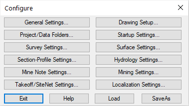
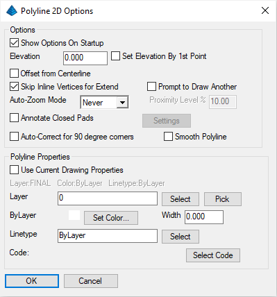
Click General Settings to display the dialog box shown here:
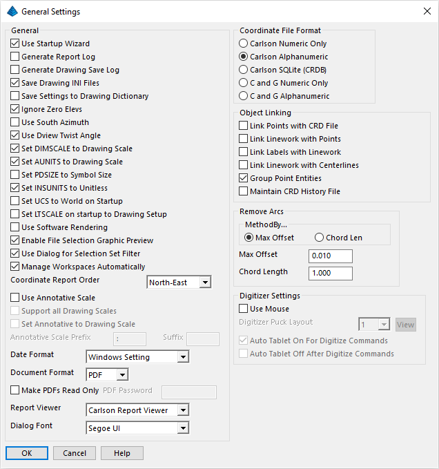
The options in this dialog box, along with the options in other Configure sub-options, determine default working conditions for Carlson. Make/set the following values:
- In anticipation of Lesson 3, make sure the Use Startup Wizard is enabled.
- Choose Carlson AlphaNumeric to provide the ability to store points in alphanumeric form (e.g. 1A, 1B, 1C, HUB5, CTRL, SS10, etc). Generally, there is a slight speed advantage to working with purely numeric point numbers. The highest numeric-only point number allowed is 99999. However, there is no limit to the number of points in an alphanumeric coordinate file.
- Enable the Group Point Entities option which groups point elevations, numbers, and descriptions (all aspects of the points) into a single entity for moving, erasing and other commands.
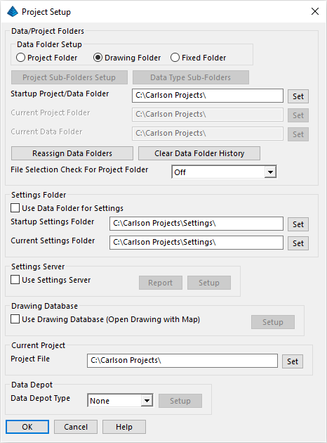
For this lesson, you will keep it simple. Enable the Drawing Folder at the top. This option will, by default, send any data files to the same folder location where the active drawing is located. Notice the Current Data Folder section at the bottom. This specifies where data files, such as .crd files in this case, are to be stored. Set the folder to C:\Carlson Projects\ and click OK to return to the main Configure dialog box.
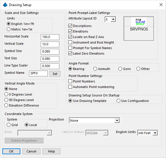
The Horizontal Scale acts as a multiplier on all text annotation. For example, 100 * Text Size (0.08) = 8 (text height of 8 CAD units). The Text Size setting is the effective height, in inches, that the text will appear when plotted at the specified Horizontal Scale (example here, 100).
Bearing and Distance labels, Legends, Title Blocks, and Point Symbols will size up or down on the basis of the Horizontal Scale set within Drawing Setup. Set the Horizontal Scale to 100 and match other settings as desired. Then click OK to dismiss the dialog box then click Exit to close the Configure dialog box. If prompted:
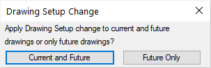
Click on the Current and Future button.
Click Points -- Set CooRDinate File to display a dialog box similar to that shown below:
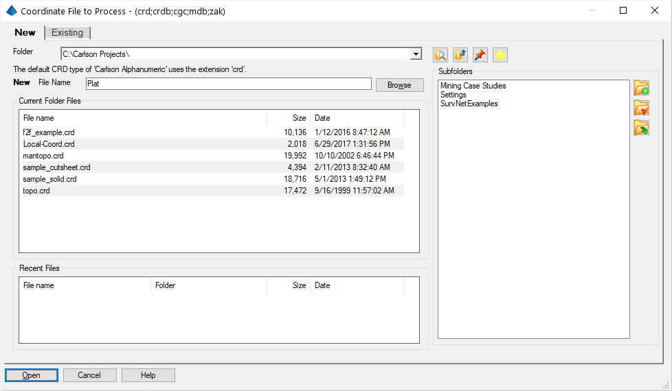
Click the New tab, as shown here. To the right of File name, type Plat and click Open. You have now created the required coordinate file.
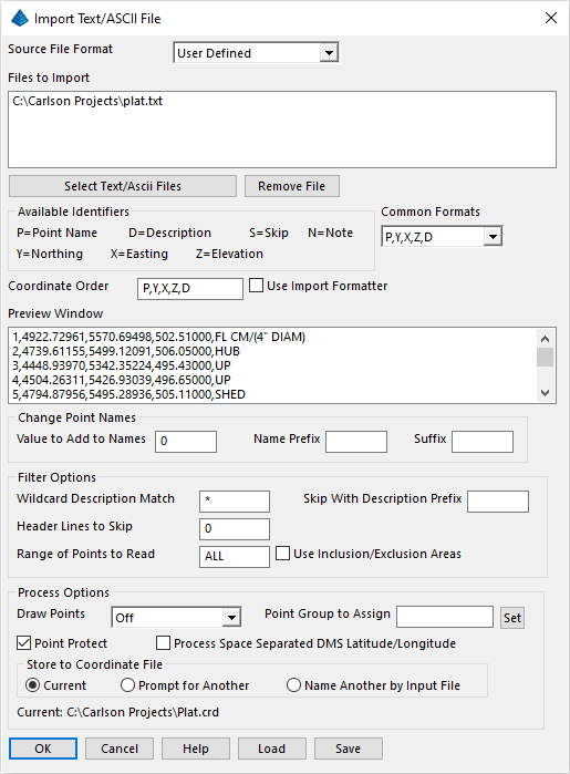
Click the Select Text/ASCII Files button and then choose Plat.txt listed in the file list. It is found in the default data folder (C:\Carlson Projects) and click Open when ready.
Plat.txt is an ASCII file containing 54 points in the form of Point Number, Northing, Easting, Elevation and Description. The format of the points appears in the Preview Window. The format is: Point (P), Northing (Y), Easting (X), Elevation (Z), Description (D), or, in short, P,Y,X,Z,D. You must match this format in the Coordinate Order. If you don't see P,Y,X,Z,D in the Coordinate Order box, then select that format from the Common Formats option. Or, you can type the list directly into the Coordinate Order box. Make sure that Draw Points is set to Off.
Click OK to save/store the data in Plat.crd. A confirming dialog appears as follows:
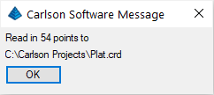
Click OK to dismiss the alert.
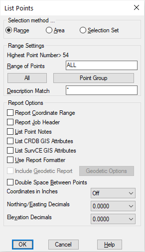
The List Points dialog box will typically default to the full range of points (ALL), which is 1 through 54 in this exercise. You can control the decimal places for the Northing/Easting and the Elevation of the points in the lower portion of the dialog box. Click OK and the settings shown above result in the report exhibited below in the Standard Report Viewer:
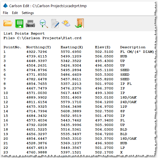
Exit the report by selecting the Exit (doorway) icon at the top of this report viewer box, or by clicking the X in the upper right of the window.
- Enable the Elevations toggle, and,
- Enable the Descriptions toggle, and,
- Use the Select Symbol button to set the Point Symbol name to symbol 0 (SPT0), which is a standard point, and,
- Enable the Automatic Point Numbering toggle, and,
- Match other settings as desired and as shown below and click OK.
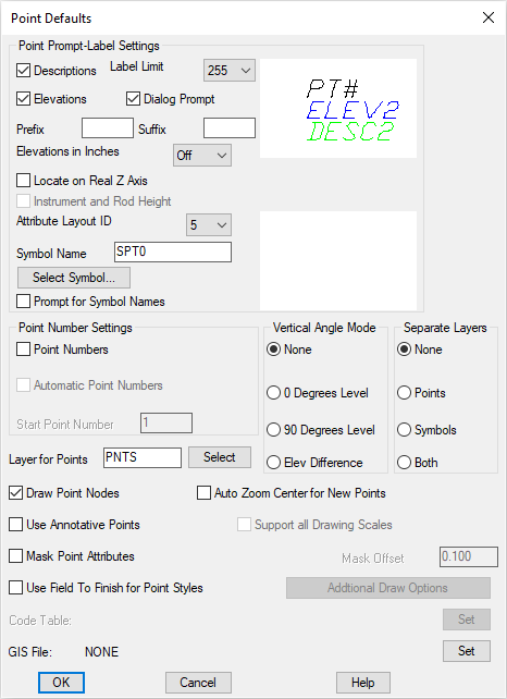
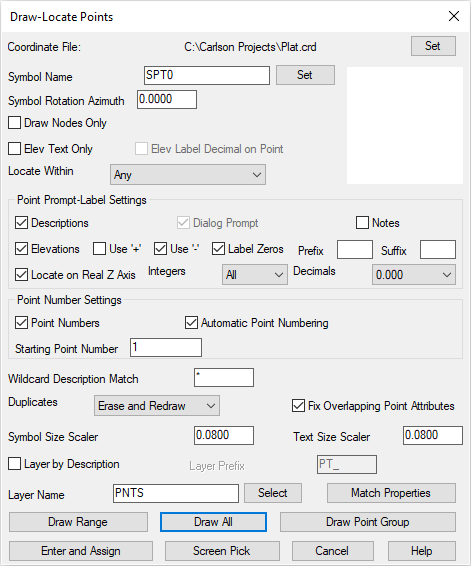
As shown in the figure shown above, the current Symbol Name is showing as SPT0, which is a standard CAD node symbol (i.e. a point). You can select a different default symbol using the Points -- Point Defaults command.
In this exercise you, let's continue to use SPT0. Later, you will add official property corner and utility symbols. Although you are working without a default symbol, there will always be a "dot" or a node at the correct insertion point of each point number.
Enable the Fix Overlapping Point Attributes toggle if it is not already checked. Click Draw All and the following dialog will display:
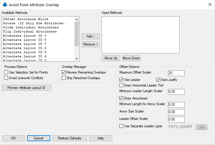
The Avoid Point Attribute Overlap dialog uses different adjustment methods, such as moving attributes and creating leader lines, to fix conflicts with the point labels. Click Cancel for now so we can view these conflicts:
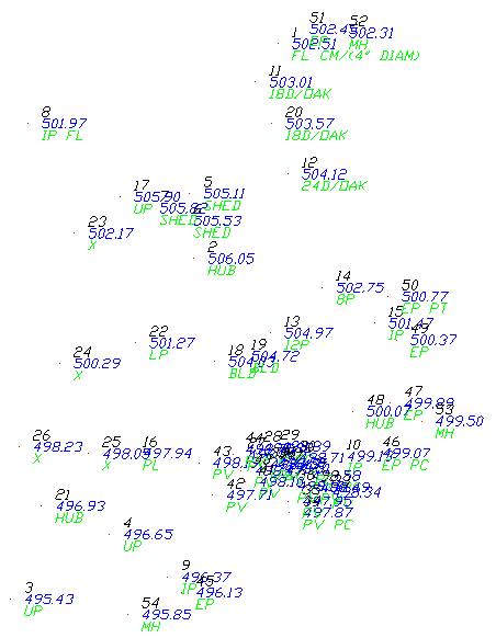
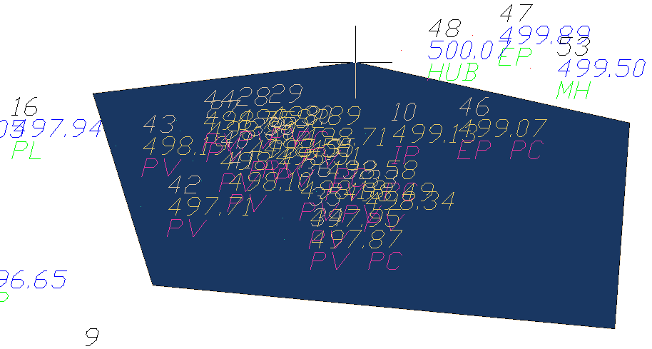
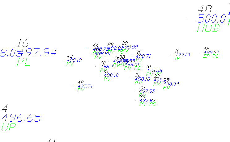
Here you have a rather busy drawing!
Here is the command line sequence, along with the responses you will enter, after clicking Resize Point Attributes command:
Method for resizing [<Scale>/Absolute]? press Enter
Scaling Multiplier <0.500>: 0.4
Scale symbols only, point labels only or both [Symbols/Labels/<Both>]? b
Select points from screen, group, or by point number [<Screen>/Group/Number]? s
Select Carlson Software points.
[FILter]/<Select entities>: wp
First vertex of inclusive polygon: click a starting point for the polygon
Next vertex: continue picking desired locations
Next vertex: when satisfied, press Enter to complete the Window Polygon
[FILter]/<Select entities>: press Enter to complete the selection set
The following shows the scaled points:
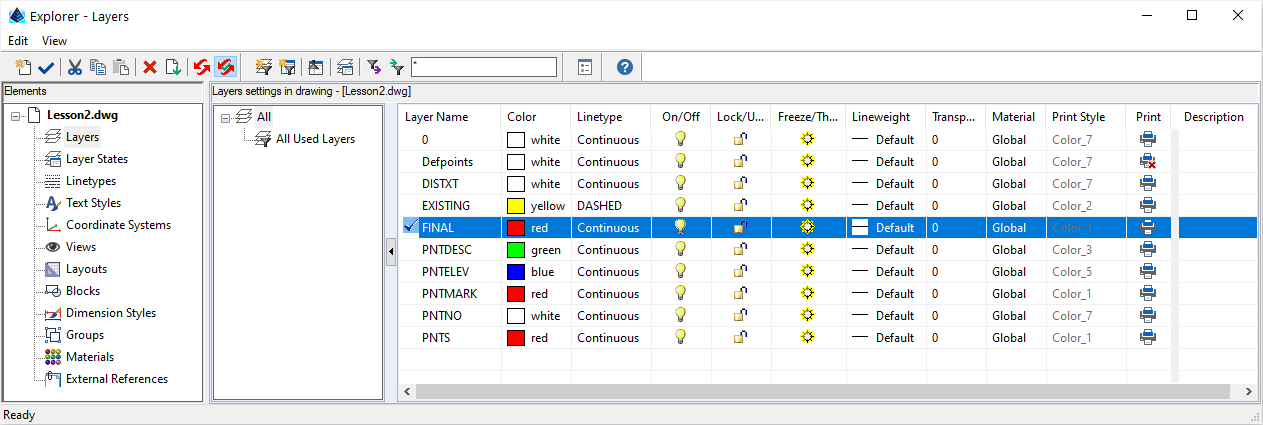
Click Final. Right click, select Current and close the Layer control.
NOTE: If the "Final" layer does not exist, create it and assign it a suggested color of red.
First, connect portions of the property line via the steps outlined below:
| Prompt(s) | Response | Narrative |
|---|---|---|
| [Continue/Extend/Follow/Options/<Pick point or point numbers>]: | 1 | This instructs the 2D polyline to commence at Point #1. |
| [Arc/Close/Distance/Follow/Undo/<Pick point or point numbers>]: | 8 | This instructs the 2D polyline to be drawn to Point 8 |
| [Arc/Close/Distance/Follow/Undo/<Pick point or point numbers>]: | press Enter | This creates a polyline. Keep this as a separate polyline because later you will turn this back lot line into a fence line. Press Enter to repeat the 2D Polyline command. |
| [Arc/Close/Distance/Follow/Undo/<Pick point or point numbers>]: | 8-10 | This instructs the 2D polyline to be drawn through Points 8, 9 and 10. |
| <Pick point or point numbers> | a | This indicates a tangential arc to be drawn starting from Point 10. |
| [Radius pt/radius Length/Arc length/Chord/Second pt/Undo/<Endpoint or point number>]: | 15 | This indicates the arc shall terminate at Point 15. |
| [Arc/Close/Distance/Extend/Follow/Line/Undo/<Pick point or point numbers>]: | 1 | This instructs the polyline to be drawn back to the starting point. The segment from 15 to 1 is not guaranteed to be tangent to the previous arc. |
| [Arc/Close/Distance/Follow/Undo/<Pick point or point numbers>]: | press Enter | This creates the full lot. |
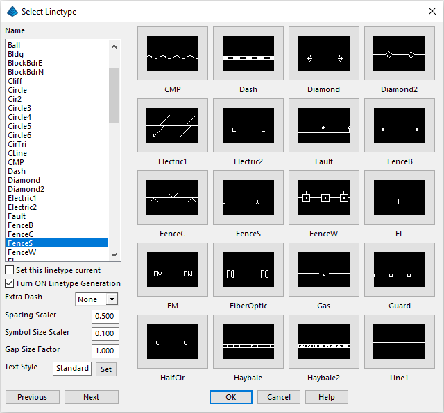
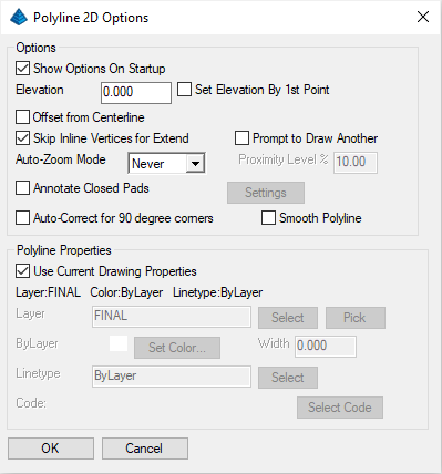
Notice in the dialog box above that the current Line Type Scaler, governing spacing, should be 0.5 (inches) and the Text (height) Scaler is 0.1. If your settings are different, you may want to set these items to match the example.
Choose the FenceS option (the solid fence line) and click OK and when prompted:
Select linework to change.
[FILter/?]/<Select entities>: pick the polyline you created from points 1 to 8
[FILter/?]/<Select entities>: press Enter
Select objects on layers to isolate.
[FILter/?]/<Select entities>: pick the property line
[FILter/?]/<Select entities>: press Enter
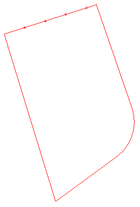
Here is the result:
Click OK. Proceed as follows to connect up the edge of pavement:
[Continue/Extend/Follow/Options/<Pick point or point numbers>]: 45-47,49-51
Press Enter at the next prompt to exit the command and create the road. Note how you can separate range entries using a comma.
When prompted:
Select polylines to smooth.
[FILter/?]/<Select entities>: pick the edge of road polyline
[FILter/?]/<Select entities>: press Enter
Offset: ENTER for Through point/<Distance>: 24
[Undo]/<Select entity>: Pick the edge-of-road polyline
[Both sides]/<Side for parallel copy>: Pick to the right of the polyline
[Undo]/<Select entity>: press Enter
[Continue/Extend/Follow/Options/<Pick point or point numbers>]: 5-7
Press Enter at the next prompt to exit the command and create two-sides of a shed as shown here:
Options/Points/<Pick a line or polyline>: Pick the shed
Options/Points/<Pick a line or polyline> (Enter to end): press Enter
Now the 2-sided building looks like this:
Click on the View -- Window and pick a lower left and upper right point that windows the driveway area. If you wish to use the View -- Previous command to zoom out, then use View -- Window to zoom in again.
Select the Draw -- 2D Polyline command and walk the polyline through the two arcs as follows:
[Continue/Extend/Follow/Options/<Pick point or point numbers>]: 27
[Arc/Close/Distance/Follow/Undo/<Pick point or point numbers>]: 28
[Arc/Close/Distance/Extend/Follow/Line/Undo/<Pick point or point numbers>]: a
[Radius pt/radius Length/Arc length/Chord/Second pt/Undo/<Endpoint or point number>]: s (Use S for 3-pt arcs)
Second point or point number: 29
Endpoint or point number: 30
[Arc/Close/Distance/Extend/Follow/Line/Undo/<Pick point or point numbers>]: 31
[Arc/Close/Distance/Extend/Follow/Line/Undo/<Pick point or point numbers>]: a
[Radius pt/radius Length/Arc length/Chord/Second pt/Undo/<Endpoint or point number>]: s
Second point or point number: 32
Endpoint or point number: 33
[Arc/Close/Distance/Extend/Follow/Line/Undo/<Pick point or point numbers>]: press Enter
In the above exercise you started at point 27, went to the PC at point 28 and inserted a 3-point arc through points 29 and 30. You proceeded on a tangent direction to point 31, which was another PC, then completed a 3-point arc through points 32 and 33, and ended. Now, connect up the basketball court area. Run the Draw -- 2D Polyline (or press Enter to repeat the previous command).
[Continue/Extend/Follow/Options/<Pick point or point numbers>]: 27
[Arc/Close/Distance/Follow/Undo/<Pick point or point numbers>]: 44
[Arc/Close/Distance/Extend/Follow/Line/Undo/<Pick point or point numbers>]: 43-39 (you can enter "backwards" ranges)
[Arc/Close/Distance/Extend/Follow/Line/Undo/<Pick point or point numbers>]: a
[Radius pt/radius Length/Arc length/Chord/Second pt/Undo/<Endpoint or point number>]: s
Second point or point number: 38
Endpoint or point number: 37
[Arc/Close/Distance/Extend/Follow/Line/Undo/<Pick point or point numbers>]: 36
[Arc/Close/Distance/Extend/Follow/Line/Undo/<Pick point or point numbers>]: a
[Radius pt/radius Length/Arc length/Chord/Second pt/Undo/<Endpoint or point number>]: s
Second point or point number: 35
Endpoint or point number: 34
[Arc/Close/Distance/Extend/Follow/Line/Undo/<Pick point or point numbers>]: press Enter
Shown below is your drawing to this point.
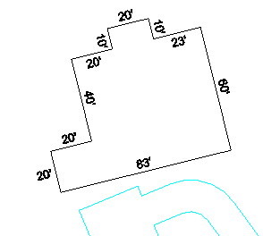
10'L, 20'R, 40'L, 20'R, 20'L, 83'L, 60'L, 23'L, 10'R.
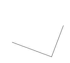
Let's begin by using the 2D Polyline (keyin 2dp) command to draw the first wall:
[Continue/Extend/Follow/Options/<Pick point or point numbers>]: 18
[Arc/Close/Distance/Follow/Undo/<Pick point or point numbers>]: 19
[Arc/Close/Distance/Follow/Undo/<Pick point or point numbers>]: press Enter
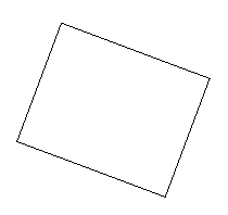
You can easily create the building "jogs" through the Edit -- Extend -- by Distance command. Complete the prompts as follows:
Pick arc, line or polyline to extend: pick the building line closer to point 18 (This makes the arrow point toward 18 rather than 19. Now you can go clockwise:)
Enter or pick distance to Draw (A,B,C,E,I,L,M,N,O,P,R,S,T,U,V,Z,?,Help): L10 (lower case "l" and "r" also work)
Enter or pick distance to Draw (A,B,C,E,I,L,M,N,O,P,R,S,T,U,V,Z,?,Help): R20
Enter or pick distance to Draw (A,B,C,E,I,L,M,N,O,P,R,S,T,U,V,Z,?,Help): L40
Enter or pick distance to Draw (A,B,C,E,I,L,M,N,O,P,R,S,T,U,V,Z,?,Help): R20
Enter or pick distance to Draw (A,B,C,E,I,L,M,N,O,P,R,S,T,U,V,Z,?,Help): L20
Enter or pick distance to Draw (A,B,C,E,I,L,M,N,O,P,R,S,T,U,V,Z,?,Help): L83
Enter or pick distance to Draw (A,B,C,E,I,L,M,N,O,P,R,S,T,U,V,Z,?,Help): L60
Enter or pick distance to Draw (A,B,C,E,I,L,M,N,O,P,R,S,T,U,V,Z,?,Help): L23
Enter or pick distance to Draw (A,B,C,E,I,L,M,N,O,P,R,S,T,U,V,Z,?,Help): C
Enter or pick distance to Draw (A,B,C,E,I,L,M,N,O,P,R,S,T,U,V,Z,?,Help): press Enter
The sewer line runs from points 52 to 53 to 54. Use the 2D Polyline command and create the sewer line as follows:
[Continue/Extend/Follow/Options/<Pick point or point numbers>]: 52-54
[Arc/Close/Distance/Follow/Undo/<Pick point or point numbers>]: press Enter
To annotate the sewer line with an S, initiate the Annotate -- Line Types -- Change Polyline Linetype command as used earlier. Within the dialog box, set the Spacing Scaler to 1.5. This will label "S" on the sewer line every 1.5" when plotted at the current scale (1"=100'). Then select the Sewer linetype from the list, and then select the sewer polyline that runs next to the road. The polyline will be annotated.
Next, create the electric utility line with the 2D Polyline which runs from point 3 to point 4 to point 17:
[Continue/Extend/Follow/Options/<Pick point or point numbers>]: 3
[Arc/Close/Distance/Follow/Undo/<Pick point or point numbers>]: 4
[Arc/Close/Distance/Follow/Undo/<Pick point or point numbers>]: 17
[Arc/Close/Distance/Follow/Undo/<Pick point or point numbers>]: press Enter
No points were taken beyond point 17, due to obstructions from the various setups in the field. So you must extend the polyline from point 17 to beyond the property. Click the Edit -- Extend -- By Distance command as used earlier. Pick on the electric utility polyline near point 17. Then pick beyond the property line and press Enter to end.
Before you annotate the electric utility line, you must offset it 25' on both sides, for a 50' total right-of-way. You will do this using Edit -- Offset -- Standard Offset command. Enter the offset distance of 25. Pick the electric utility polyline and then pick to one side for the first offset. Repeat for the other side, by first picking the electric utility polyline, then picking the other side for the offset. Press Enter to end.
The next task will be to annotate the central electric line using the Annotate -- Line Types -- Polyline to Special Line command. Choose the Electric linetype, which appears on the third page of linetypes and then click OK. Then select the electric utility polyline to annotate it, and press Enter.
New width <0.00>: 1.5
Select polylines to change width of.
[FILter]/<Select entities>: Pick once for the fence line portion
[FILter]/<Select entities>: Pick once for the remaining property lines
[FILter]/<Select entities>: press Enter
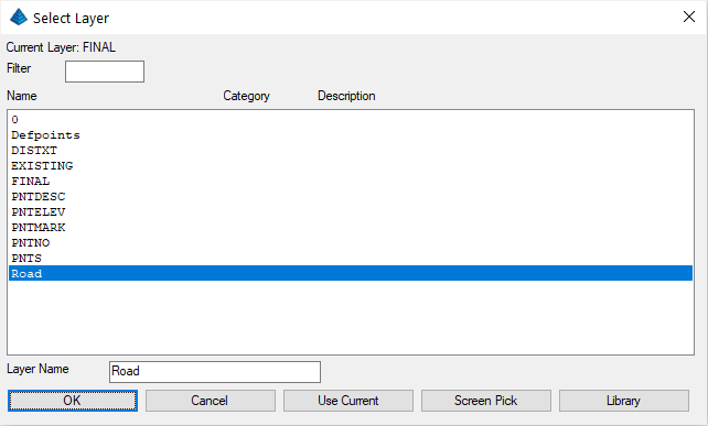
- Click the New Layer button, and enter the name Road for the new layer.
- Choose the color Cyan by clicking the color square to the right of the layer name.
- Close the dialog.
Select entities to be changed.
[FILter]/<Select entities>: Pick all driveway and road entities
[FILter]/<Select entities>: press Enter
Specify new layer [Name/Current/<pick entity>]: n
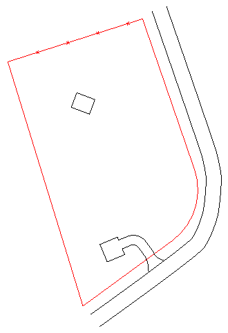
This brings up the dialog box shown below. Select Road and click OK.
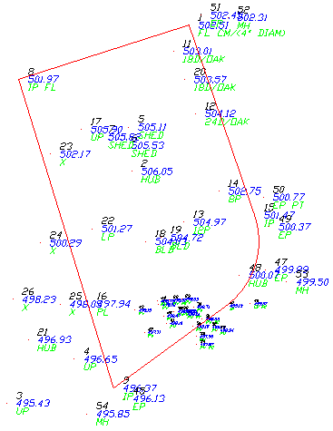
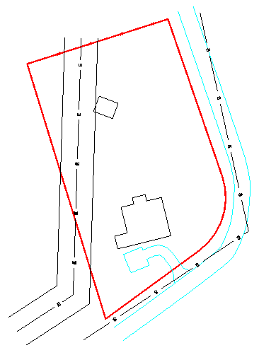
Your linework is now complete and is shown below:
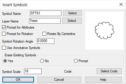
The various items to place are summarized below:
Small Deciduous Tree: Symbol: SPT61, Layer: Trees, Size: 18
Options/Select entities/Enter coords/<Pick point or point numbers>: 11
Options/Select entities/Enter coords/<Pick point or point numbers>: 20
Options/Select entities/Enter coords/<Pick point or point numbers>: press Enter
Press Enter to re-run the command for:
Large Deciduous Tree: Symbol: SPT61, Layer: Trees, Size: 24
Options/Select entities/Enter coords/<Pick point or point numbers>: 12
Options/Select entities/Enter coords/<Pick point or point numbers>: press Enter
Press Enter to re-run the command for:
Small Coniferous Tree: Symbol: SPT53, Layer: Trees, Size: 8
Options/Select entities/Enter coords/<Pick point or point numbers>: 14
Options/Select entities/Enter coords/<Pick point or point numbers>: press Enter
Press Enter to re-run the command for:
Found Iron Pins: Symbol: SPT5, Layer: FINAL, Size: 8
Options/Select entities/Enter coords/<Pick point or point numbers>: 8-10,15
Wildcard match of point description <*>: press Enter
Options/Select entities/Enter coords/<Pick point or point numbers>: press Enter
Press Enter to re-run the command for:
Concrete Monument: Symbol: SPT13, Layer: FINAL, Size: 8
Options/Select entities/Enter coords/<Pick point or point numbers>: 13
Options/Select entities/Enter coords/<Pick point or point numbers>: press Enter
Press Enter to re-run the command for:
Sewer Manholes: Symbol: SPT34, Layer: FINAL, Size: 8
Options/Select entities/Enter coords/<Pick point or point numbers>: s (the following dialog box appears, click OK:)
Select arcs, circles, faces, points, text, lines and polylines.
[FILter]/<Select entities>: pick the Sewer polyline
[FILter]/<Select entities>: press Enter to terminate the selection option
Options/Select entities/Enter coords/<Pick point or point numbers>: press Enter
The symbols are inserted at the three polyline endpoints.
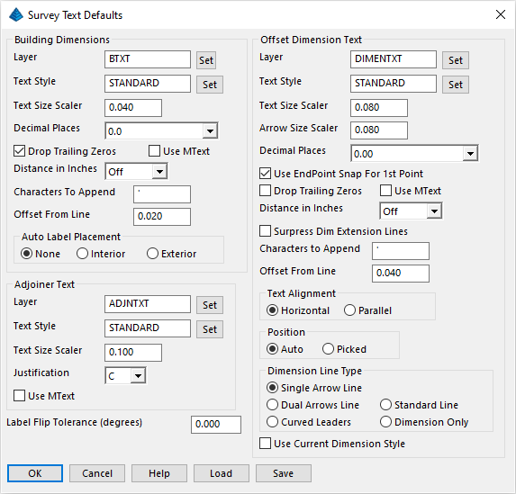
The changes you will make are in the upper-left section "Building Dimensions." Change the following:
- set the Layer to BTXT, so that building dimensions can be frozen to reduce the clutter even more. It is generally a good strategy to use layers for selective freezing and thawing.
- set the Text Size Scaler to 0.04
- enable the Drop Trailing Zeros (this option will label 17.0' as 17').
- set the Offset From Line to 0.02.
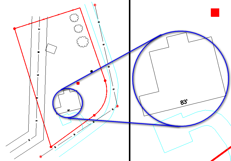
If you had dragged the cursor to the left rather than to the right, with the same near-parallel angle to the line, the 83' would be drawn below the building rather than above.
Another example is shown below. Select Annotate -- Survey Text -- Building Dimensions and click on the left-most segment of the building. Then click roughly perpendicular to the left. This creates a perpendicular, rather than parallel, label as shown below.
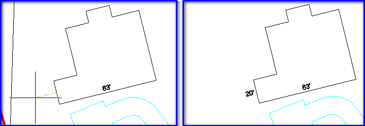
Label the rest of the building. Notice that the sides of the building that you are dimensioning are measured in even feet. Because you had selected the Drop Trailing Zeros option when you set the Survey Text Defaults (and even with the Decimal Places defaulting to 0.00), the ".00" is not reflected in the labels:
NOTE: If you choose the wrong direction while you are labeling, a suggestion would be to re-pick the segment and place it in the correct direction and complete the command. Then Erase the undesired label(s) at the conclusion of the command.
Re-issue the Annotate -- Survey Text -- Survey Text Defaults command. The dialog previously shown will reappear. Change the following in the Offset Dimension Text grouping:
- set the Text Size Scaler to 0.04
- set the Arrow Size Scaler to 0.04
- enable the Dual Arrows Line option
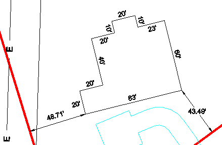
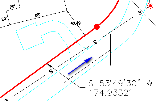
[end on] Pick Bldg/Object Corner: pick on the SE building corner
[perp] Pick Line To Offset From: pick on the South property line (before the arc, near the end of the driveway)
The setback is labeled 43.49'. Note the distance suffix is/was labeled as an apostrophe "'" rather than "ft." If you desire an alternate label, re-examine the Characters to Append control of the Survey Text Defaults command.
Re-issue the Annotate -- Survey Text -- Survey Text Defaults command. The dialog previously shown will reappear. Change the following:
- set the Text Alignment to Parallel
[end on] Pick Bldg/Object Corner: pick on the SW building corner
[perp] Pick Line To Offset From: pick on the West property line (avoid the electric right-of-way lin
The result is shown below:
Notice within the above prompts, the use of the [end on] and [perp] snaps. When Carlson sets a snap for temporary use, it displays the snap within the brackets as shown. A building corner is always an endpoint, so the end snap always applies to the first pick. The offset is the perpendicular distance to the property lines, so the [perp] snap always applies to the second pick. The per (perpendicular) snap applies to offsets from arcs as well. In the case of arcs, the per snap finds the shortest, radial distance to the arc.
You could use the Offset Dimension command to label the Electric utility right-of-way distance of 50' total by entering nea (for nearest snap) for the first pick, then entering the default per snap for the second pick on the other side of the right-of-way.
- set the Adjoiner Text Justification to C for centered
- set the Text Size Scaler to 0.06
Pick Line Or Polyline: pick the west property line
Starting point: pick a centering point west of the property for the adjoiner text
Enter text at the cursor, press Enter to finish the command... supply the text as follows:
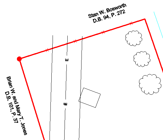
Brian W. and Mary T. Jones (press Enter)This produces parallel, center-justified text on the west side of the property. Press Enter to repeat the command and complete the following prompts:
D.B. 101, P. 37 (press Enter twice)
Pick Line Or Polyline: pick the north property line
Starting point: pick a centering point north of the north property line
Enter text at the cursor, press Enter to finish the command... supply the text as follows:
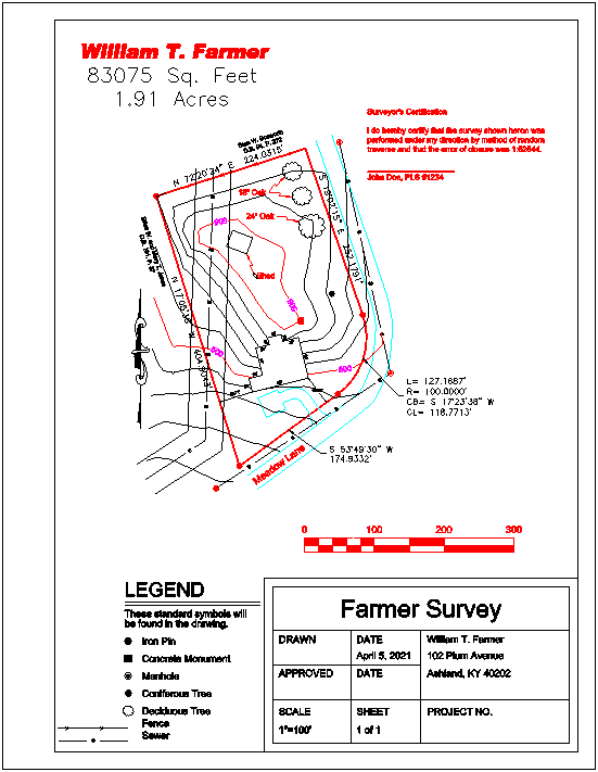
Stan W. Bosworth (press Enter)The results are shown here:
D.B. 94, P. 272 (press Enter twice)
Select line or polyline [Size/Points]: pick the northern property line to the east, or right side. The bearing direction will be labeled towards the picked end, which is Northeast.
Select line or polyline [Size/Points] (Enter to end): pick the eastern property line closest to the southern endpoint of the line
Select line or polyline [Size/Points] (Enter to end): press Enter
To label the western property line on the lower (western) side of the line, select the the Annotate -- Angle/Distance -- _BearingDistance option to place Bearing and Distance below the line and follow the prompts below:
Select line or polyline [Size/Points]: pick the western property line closest to the northern endpoint of the line
Select line or polyline [Size/Points] (Enter to end): press Enter
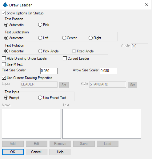
To label the southern line segment with a leader, run the Annotate -- Annotate with Leader -- Brg-Dist with Leader command and follow the prompts below:
Select line or polyline [Options/Size/Points]: pick the southern property line segment on the southwest side
Pick end point for leader: pick a point for the label position
Select line or polyline [Options/Size/Points] (Enter to end): press Enter
Options/Points/<Select arc>: type O for Options and the Stack Label Arc dialog box appears
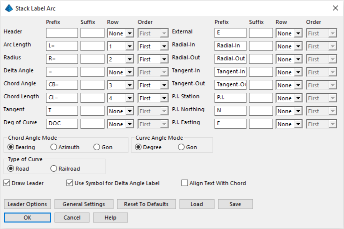
Set the sequence column to 1, 2, 3 and 4 as shown. When you are done with the dialog box, click OK to resume the command prompts:
Options/Points/<Select arc> (Enter to end): pick the arc
Pick end point for leader: pick a point to the right to place the label. As the cursor moves, the text "ghosts" which allows you to make the best possible placement decision
Options/Points/<Select arc> (Enter to end): press Enter
Click OK and complete the prompts as follows:
Options/Size/Pick Arrow Location: pick near the southernmost corner of the shed
Text location: pick slightly down and to the right
Text: Shed
Text: press Enter
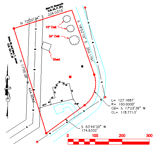
Repeat the process for all the special leader text items shown in the drawing below. In the case of the 18" Oak trees, create just one leader with text and on the second oak tree, create only the leader and then press Enter when asked for Text.
Your drawing should be similar to this one:
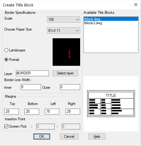
Choose paper size A1 (portrait view, 8½ by 11) and click OK. Pick a point below and to the left of the survey in order to locate the lower-left corner of the border outer line. Remember that the title block will be at the bottom, so leave extra room at the bottom.
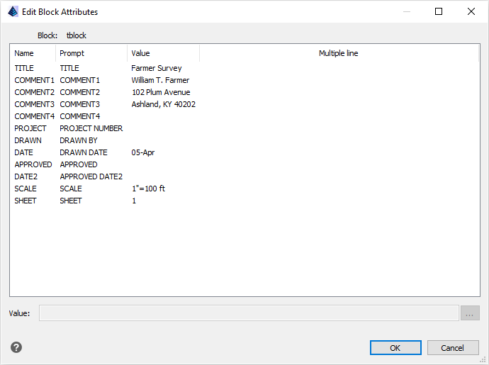
The following dialog appears, prompting you for the attributes of the title block. Be sure to also click Next in order to enter in more attributes.
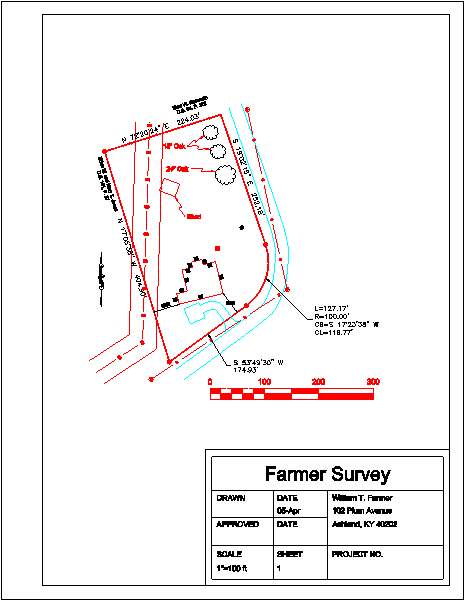
Your drawing should resemble the one shown below:
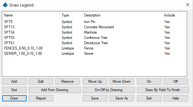
If you want to change the order of the items in the list, use the Move Up and Move Down buttons, after first selecting and highlighting the item to be moved. After the list is ordered correctly, highlight one item on the list and click the Edit button to edit the symbol definition. Edit each symbol definition individually and type the following descriptions in the description box:
- SPT5 = Iron Pin
- SPT13 = Concrete Monument
- SPT34 = Manhole
- SPT53 = Pine Tree
- SPT61 = Oak Tree
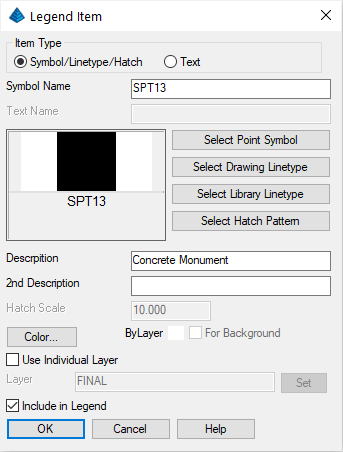
Save the completed legend which is shown below:
Select the Draw option from the Legend Definitions dialog box. Set the defaults as shown below:
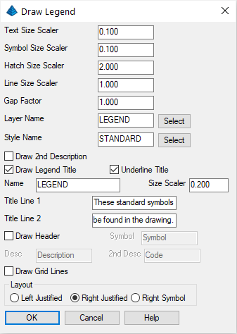
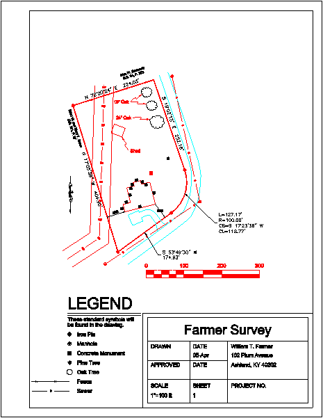
Click OK. Pick a point for the legend at a coordinate location approximately at 5311.5,4275 (CAD coordinates) then click Exit. You may need to adjust the position and/or portions of the legend to fit in the tight space. You also may need to move the previously drawn bar scale. Use the Move command to do this. The following shows the drawing to this point:
NOTE: If you wish to reset the spacing of the sewer and electric utility annotation, set a desired value for the LTSCALE box in the Settings -- Drawing Setup dialog box (the setting is 50 in this example).
At the command line, type dtext and complete the following prompts:
Specify start point of text or [Justify/Style]: j
Enter an option [Left/Center/Right/Align/Middle/Fit/TL/TC/TR/ML/MC/MR/BL/BC/BR]: r
Right point of text: pick a point as shown below, just to the left of the leader annotation
Height of text <8.00>: 10
Rotation angle of text <E>: pick a point as shown below by the location of the crosshair
Text: Meadow Lane
Text: press Enter
This right-justifies the label Meadow Lane, ending it before it contacts the leader line.
Now you will enter a certification using MText. The MText command stretches an entire block of text. This command breaks up the lines in the block of text depending on how you edit and adjust the MText window. First, use the View -- Extents command to view the entire drawing. Then type mtext at the command line and follow the prompts:
Multiline Text: First corner for block of text: 5660,4980 (or pick an approximate location)
[Justification/Rotation/Style/Height/Width]/<Opposite corner for block of text>: pick a point below and to the right of the first, but inside the inside border line
You now see the MText interface that displays word-processing style editing options. Indicate text height of 8 (press Enter to commit) then type the following into the dialog box:
Surveyor's CertificationThe command "wraps" the text when it runs out of space in the MText window. Click OK at the upper right to place this text into the drawing.
I do hereby certify that the survey shown heron was performed under my direction by method of random traverse and that the error of closure was 1:52544.
____________________
John Doe, PLS #1234
After the MText is placed, you can click on the text to activate the grips. All four corners highlight as grips. When you pick on a grip, you can expand or change the shape of the MText rectangle. When you do this the text adjusts automatically, wrapping into more or fewer lines of text based on the size of the MText window. You can also move the entire text block to a new location.
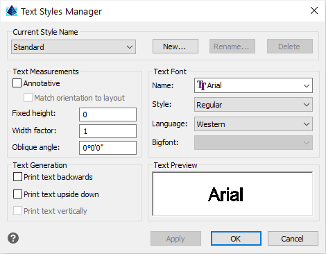
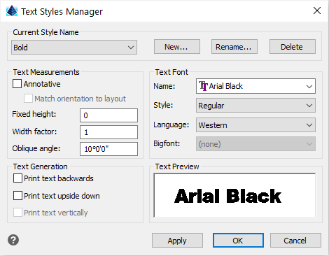
Click New, enter Bold in the New Text Style dialog, and click OK.
Define the Bold style consisting of the Arial Black font and an Oblique Angle of 10° by entering the settings as show below:
Then click OK. Now, run the DText command by typing dtext at the command line, and place the text at the top of the drawing as follows:
Specify start point of text or [Justify/Style]: pick a point near the northwest corner of the drawing
Height of text <8.00>: 20
Rotation angle of text <N53d56'51"E>: E (for due East)
Text: William T. Farmer
Text: press Enter
Select the Area/Layout -- Area by Lines & Arcs command. When prompted to Select objects, pick the two polylines that taken together, completely enclose the property.
Pick an area labeling centering point for the area label under the William T. Farmer title at the top of the drawing.
Initiate the Surface -- Triangulate & Contour command. On the Triangulate tab, set the following values:
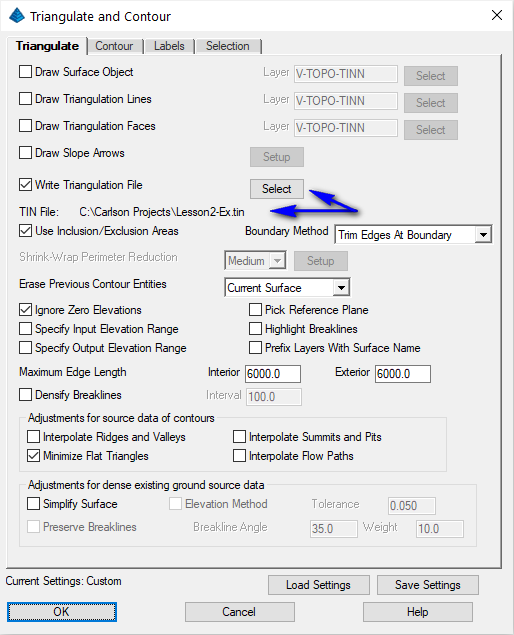
Also make sure to enable the Use Inclusion/Exclusion Areas option. Navigate to the Contour tab and set the Contour Interval to 1.0. Click OK and then answer as follows:
Select Inclusion perimeter polylines or ENTER for none.
[FILter]/<Select entities>: press Enter for none.
Select Exclusion perimeter polylines or ENTER for none.
[FILter]/<Select entities>: select the building and the shed, and then press Enter. Since the building and shed are closed polygons acting as exclusion perimeters, the contours will not pass through them when they are created.
Select points and breaklines to Triangulate.
[FILter]/<Select entities>: all
[FILter]/<Select entities>: press Enter
The contour map is created. Freeze the points again by using View -- Freeze Layer by Select and picking one of the points.
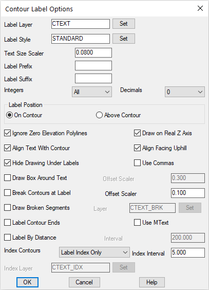
Specify the surface model (*.tin) created earlier and click the Open button on the Carlson File Selector dialog box. Now pick two points that cross through one or more Index contours. The contours are automatically labeled using the specified text style.