This command reports the bearing/azimuth and horizontal distance between two points. The command prompts for a series of points. Use the appropriate object snap mode to select the points from the screen, or use the point numbers to reference coordinates stored in the current coordinate (.CRD) file. The results are then displayed. This command is also used in conjunction with the Traverse and Sideshot commands to occupy and backsight two points. The last two points you Inverse to are the Backsight and the Occupied point for the Traverse and Sideshot commands. An attractive feature of Inverse is that you can enter T or SS within the command and go directly to Traverse or Sideshot. Even a single S will transmit to Sideshot. Hotkeys are not case sensitive. Press [Enter] at the point prompt to end the command.
You can also inverse around an arc by inversing to the Point of
Curvature (PC), and then entering an A for Arc option. The program
will ask for the radius point, the curve direction left or right
and the PT point. The curve data is then reported. There is an
unequal PC-Radius and PT-Radius distance check. The tolerance for
this is set in the Area Label Defaults command.
After picking the first point, there is a keyboard option for
Multiple which will prompt for a range of point numbers to report
as a sideshot inverse.
There are several input options for Inverse that are set
by entering O for Options on the command line. Sideshot inverse
holds the current occupied point and calculates the
bearing/distance to each entered point. The Pairs option reports
the bearing/distance between pairs of points and not for every
entered point. For example, if points 1,2,11,12 were entered, the
bearing/distance would be reported for 1,2 and 11,12 but not 2,11.
The Auto Increment option uses the next point number by just
pressing Enter. To exit the routine with Auto Increment active, End
must be entered.
The Auto Zoom settings
under Inverse Options will zoom the display as needed to have the
occupied point or both the occupied and backsight points visible.
The Report Total Distance
option displays a running total of all inversed distances during
the current run of the routine.
The Report Geodetic Mean Bearing option reports the geodetic
bearing at the to point (forward), at the from point (back) and the
mean bearing. The geodetic distance is also report for the geodetic
distance at zero elevation and at ground elevation. The coordinates
are converted to lat/lon using the projection setup under the
Drawing Setup command. The program reports that lat/lon,
convergence angle and grid scale factor at the from and to points.
Here's an example for SP83 VT,
Northing(Y) Easting(X) Elev(Z)
218623.2996 485210.2502 0.0000
Northing(Y) Easting(X) Elev(Z)
218439.0529 487144.1875 0.0000
Bearing: S 84°33'28" E Horizontal Distance: 1942.6941325
Lat: 43°01'05.81806" Long: -76°49'09.53807"
Convergence: N 02°56'59" E Scale: 1.0014892493
Lat: 43°01'04.98404" Long: -76°48'43.45145"
Convergence: N 02°56'41" E Scale: 1.0014841465
Geodetic Forward Bearing: S 87°30'28" E
Geodetic Back Bearing: S 87°30'09" E
Geodetic Mean Bearing: S 87°30'18" E
Geodetic Distance: 1942.984 Zero Elev, 1942.984 Ground Elev
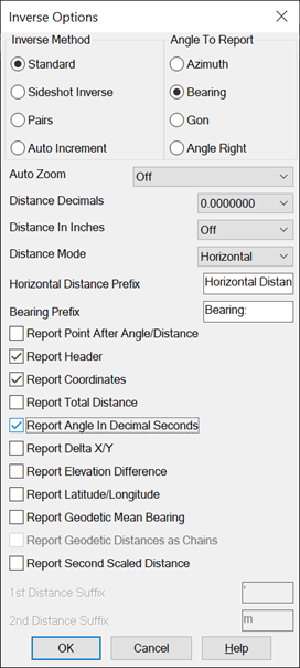
There are also several angle output options that are set at the
second prompt in Options. The angle can be reported as either
Bearing, Azimuth, Gon or Angle Right. You can also specify to
report angles with decimal seconds. The distance settings include
the number of decimals for distances, whether to report slope or
horizontal distance and whether to report distances in feet and
inches format. The Report Total Distance option will report the
cumulative distance for all the inverses. The Report Delta X/Y will
distances as delta north-south-east-west instead of angle and
distance. For Report Latitude/Longitude, the grid projection must
be set in Drawing Setup. The Report Point After Angle/Distance
controls whether the point coordinates are reported before or after
the angle and distance. The Report Header controls whether to have
a header label line for the point data. The Report Coordinates
option choose whether to report the northing, easting and elevation
of the points. The Report Elevation Difference option will report
the delta Z between the pairs of points. The Report Second Scaled
Distance option will report a second distance value that is scaled
from the first distance value using the scale factor defined in
Drawing Setup. When the Second Scaled Distance option is on, there
are settings for the suffix to use for both the first and second
distance to help identify them separately in the report.
For instruction on how to insert either new or existing points
into the drawing, see Draw-Locate Points in the Points Commands
section of the General Commands chapter.
Calculate Bearing & Distance from starting point?
Traverse/SideShot/Options/Arc/Multiple/Pick point or point
number: pick a point
Traverse/SideShot/Options/Arc/Multiple/Pick point or point
number: 9
PtNo.
Northing(Y) Easting(X)
Elev(Z) Description
9
4909.25
4648.37
0.00
Bearing: N 81d8'54"
E Azimuth: 81d8'54"
Horizontal Distance:
261.17407461
Pulldown Menu Location: COGO
Keyboard Commands: inverse, i
Prerequisite: None
| Converted from CHM to HTML with chm2web Standard 2.85 (unicode) |