
This command is used to create point groups based on inclusion and exclusion filters. The manager can perform various functions on these point groups. Also point groups can be referenced by group name in other commands such as Field to Finish and Data Collection.
Create Point
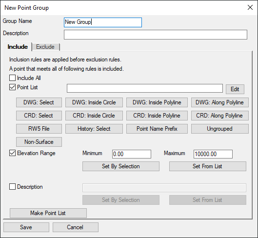
Group: This routine creates point groups. When selected, the
New Point Group dialog box is displayed.
 Group
Name is the name of Point Group to create.
Group
Name is the name of Point Group to create.
Description is the description of Point Group to create.
Use the Include Tab to define the filters to be applied when creating the point group. Inclusion rules are applied before the exclusion rules.
When Include All is toggled on, all points in the coordinate file will be included in the selection.
When Point
List is toggled on, an option of defining the point list can
be selected or the point numbers can be manually entered in the
edit box. The points retain the order entered in the edit box which
can be used in other point functions that process points where the
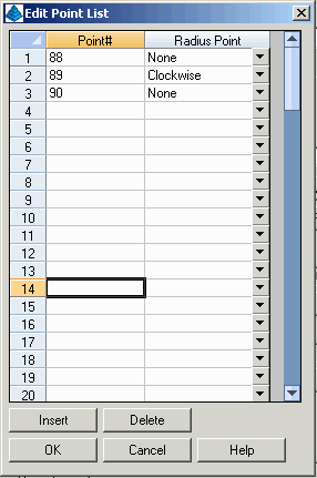
order matters such as Legal Description. The Edit button brings up
a spreadsheet editor for the point list and there is a flag for
each point for whether the point is a radius point. This radius
point flag is used in routines that process points for a polyline
or perimeter such as Legal Description. The radius point is used to
define an arc in the polyline. The sequence of points for the arc
are PC, radius point and PT.

DWG: Select allows for manual selection of the points to include from the drawing. The points must be drawn on the screen prior to using this option. All standard AutoCAD selection tools, are available for selection of the points.
DWG: Inside Circle allows for selection of the points to include by a user defined circle. The circle is defined by specifying the center and radius of the circle. The radius can be defined by entering in a numeric value or by picking on the screen. Points must be drawn to the screen prior to using this option.
DWG: Inside
Polyline allows for the selection of points to include by
referencing a closed polyline. All points located within the closed
polyline will be included in the selection. Prompts for the
inclusion polyline and the exclusion polyline will display. The
inclusion polyline limits of the selection area. The exclusion
polyline defines the area to exclude within the inclusion polyline.
Points must be drawn to the screen prior to using this
option.
DWG: Along
Polyline allows for the selection of points to include by
offset from an alignment polyline. All points located within the
specified offset tolerance from the polyline will be included in
the selection.
CRD: Select allows for manual selection of the points to include from a point list. Standard window selection tools are available for selecting the points to include.

CRD: Inside Circle allows for selection of the points to include by a user defined circle. The circle is defined by specifying the center and radius of the circle. The radius can be defined by entering in a numeric value or by picking on the screen. The points do NOT have to be drawn to the screen prior to selection.
CRD: Inside Polyline allows for the selection of points to include by referencing a closed polyline. All points located within the closed polyline will be included in the selection. Prompts for the inclusion polyline and the exclusion polyline will display. The inclusion polyline limits of the selection area. The exclusion polyline defines the area to exclude within the inclusion polyline. The points do NOT have to be drawn to the screen prior to selection.
CRD: Along
Polyline allows for the selection of points to include by
offset from an alignment polyline. All points located within the
specified offset tolerance from the polyline will be included in
the selection.
RW5 File: creates a list of points from all
the point numbers used in the selected RW5 raw data file.
History Select: creates a point group by
date range using the log stored in the CRD history. See Coordinate
File Utility > Point History to review this information.
Point Name Prefix: creates a point group by
a specified number of digits from the start of point names. This
method applies when your point numbering method uses a fixed
beginning string for point names. For example, if point names begin
with a code for the crew, then this method can make point groups
per crew.
Point Name Suffix: creates point groups
using alpha characters that follow numbers in the point
names.
Ungrouped: creates a point group including
any points that are not already part of another group.
Non-Surface: creates a list of points that
are set as Non-Surface points to be skipped in surface
modeling.
Set By Selection allows for selection of points to include in the group from the drawing. The points must be drawn to the screen prior to using this selection method. Standard AutoCAD selection methods are available.
Set From List allows for selection of points to include in the group from a point list. Standard Windows selection tools are available with this option.
The Description option allows for a
selection of points to include based upon the description of the
point. The description to filter for can be entered in the data
field or by using the Set By Selection and/or the Set From List
options described above.
Make Point List converts the group
definition to a list of point numbers that currently match the
group definition.
The Exclude Tab allows for defining rules that pertain to the points to be excluded from the Inclusion selection. After defining the inclusion rules for the group, the options on the Exclude tab can be used to filter for points to exclude from the group. For example, if the inclusion rules call for all points within the elevation range of 8 to 12, an exclusion rule can be set to exclude the points on elevation 9 or with the description tree. The options on this tab work exactly like the options on the Include tab. Please refer to the Include tab definitions for further instruction.
Save Changes saves the point group to the group name specified based upon the Inclusion and Exclusion rules specified.
Cancel Changes discards specified rules and changes and goes back to the Point Group Manager dialog.
Edit Point
Group: This function allows for editing of existing point
groups. From the list of available groups, highlight the group or
groups to edit. When complete with the first group, if more than
one is selected, selecting the Save Changes option will save the
changes to the active group and switch to the next group in the
selection set.
From the Groups pulldown, select Edit Groups, the Edit Group dialog box will now appear.
See Create Point Groups for further definitions of the available options.
Delete Point Group: This deletes specified groups for the existing group list. One or more groups can be deleted at one time.
Copy Point
Group: This routine creates a new point group by copying the
currently highlighted group. This allows you to modify an existing
group definition and create a new group.
Import Point Groups: This allows for
importing filters from point group manager settings of other
coordinate files. This is a useful option when coordinate files are
going to contain same point group names with the same filters. This
option only brings in the filters into the point group manager, it
does not import actual points into the coordinate file by group
name. Existing points in the active coordinate file that meet the
filter definitions of the imported point groups will automatically
be added to the corresponding group.
Insert into Drawing: This routine draws the points in the group in the drawing. Individual points or point ranges can be selected from the group to be erased from the drawing. For example points 264-275 and point 298 contained in group Wet Lands are tagged to be erased from the drawing in the following figure.

The symbol to be used and the attribute layout are determined by the Point Default Settings. The symbol size and the point attribute size are determined by the settings in the Drawing Setup routine.
Erase from
Drawing: This erases specified point group/groups or
specified points from within the group from the drawing.
Erase from Coordinate File and Drawing: This erases the points in the specified group/groups or specified points from within the group from the drawing and will also permanently delete the points from the CRD file. You will be prompted with a warning as follows:
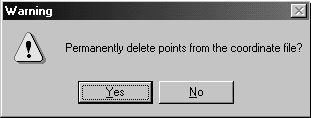
Selecting Yes will complete the command and erase the points from the screen and also the coordinate file. Selecting No will cancel the command leaving the drawing and the coordinate file unchanged.
Report: The routine will generate a point list of the points contained in the selected group/groups or specified points from within the group.
Highlight:
This routine highlights the specified objects in the drawing. This
makes them distinguishable from the other points on the
screen.
Isolate: This routine freezes all the points
except for the current group.
Freeze: This routine freezes the points of the highlighted point group like the Points->Freeze Points command.
Thaw: This routine thaws the points of the highlighted point group like the Points->Thaw Points command.
Thaw All: This routine thaws all the points like the Points->Thaw Points command.
Draw 2D
Line: This routine draws a 2d polyline between the points
contained in the group/groups or between specified points in a
group.
Renumber: Renumbers points in the current
group.
Edit Attributes: Edits the point attributes
for the points entities in the drawing.
Edit Descriptions: Sets the description for
the points in the current group.
Edit Elevations: Sets the elevation for the
points in the current group.
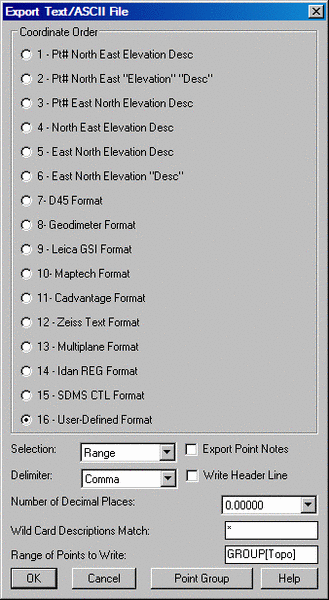
Export: This command exports the selected group/groups or the specified point(s) or range of points from within the group to various formats. The available formats are ASCII/Text, Carlson Software CRD and C&G CRD files.
When ASCII/Text is selected, the Export Text/ASCII File dialog box will be displayed. Please refer to the Export Text/ASCII File section of the manual for more information.
The CRD-Carlson
software command writes the selected group/groups or the
specified point(s) or range of points within the group to a new
Carlson formatted CRD file.
Specify the file name of the CRD file to create and press save.
CRD-C&G writes the selected group/groups or the specified point(s) or range of points within the group to a new C&G formatted CRD file.
Specify the file name of the CRD file to create and
press save.
The series of buttons at the bottom of the main
dialog do the same functions as the routines in the Groups
pull-down menu except the Move Up and Move Down which are only
available as these buttons. The Move Up/Down simply change
the display order of the groups in the list. The Import
function brings in group definitions from either another coordinate
file or from a C&G Points List File. The Sort function
sorts the groups by name or by number of points. The Merge
function combines the definitions from two or more existing groups
to create a new group. To run Merge, highlight the groups to merge
in the Groups list by clicking on them while holding the Ctrl key,
and then pick the Merge button.
Pulldown Menu Location: Points
Keyboard Command: pgm
Prerequisite: A coordinate file
| Converted from CHM to HTML with chm2web Standard 2.85 (unicode) |