Config Menu
5.03 CAD Configuration (CM)
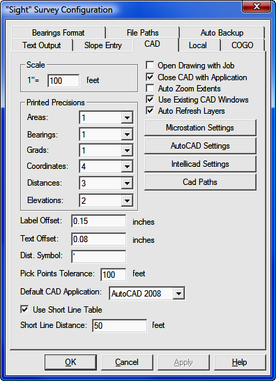
FUNCTION: The CAD Configuration menu controls scaling and paper options, the printed precision of CAD annotation, and other CAD options.
Activate the CAD Configuration routine by picking from the Config menu; by pressing [Alt][O], [C], or by typing the two-letter command CM at any data entry prompt.
|
CAUTION: Several configuration menu settings are dependent upon settings from other menus. For example, setting the directional units to Grads on the Local Configuration menu (LC - Section 5.05) will affect your options the CAD, Text Output, and Bearings Format menus. However, you must remember to click [Apply] at the bottom of the menu before any changes you make are accepted. Simply clicking on an item or changing a value does not change the setting unless you click [OK] or [Apply]. Clicking [Apply] will keep the configuration menu group open for multiple changes, while clicking [OK] will apply the changes and exit the menus. |
Scale: Enter your scale in English or metric units. The units are controlled by your selection of Distance Units in the Local Configuration menu (LC - Section 5.05). The value you enter here is your anticipated drawing scale and it is used to correctly size symbols and text annotation.
Printed Precisions: Printed precision is nothing more than the number of places to which your CAD annotation will be carried out. The settings here are for CAD annotation only. Printed precision tor text output is set under the Text Configuration menu (KT - Section 5.01). Settings for printed precision have nothing to do with the internal precision of calculations.
Your choices are: Area - 0 to 6; Bearings - 0 to 3 (seconds value) , or nearest minute, or nearest degree in degrees, or 0 to 6 in grads; Grads - 0 to 6; Coordinates - 0 to 8; Distances - 0 to 6; Elevations - 0 to 6.
Label Offset: Enter the distance of separation from the point to the point label. This is the actual distance between the two elements when the drawing is plotted at the specified scale. The units are controlled by your selection of Distance Units in the Local Configuration menu (LC - Section 5.05).
Text Offset: Enter the distance of separation from line annotation to the line. This is the actual distance between the two elements when the drawing is plotted at the specified scale. The units are controlled by your selection of Distance Units in the Local Configuration menu (LC - Section 5.05).
Dist. Symbol: Enter the distance symbol you would like to have as a suffix to your numerical data. This could be a foot mark ( ' ), or a letter or letters such as m for meters or ft for feet. The maximum field size is four characters.
Pick Points Tolerance: When selecting a point from the CAD window, "Sight" Survey will use a pick point tolerance to locate any point within the specified distance from the mouse cursor. To increase the tolerance or area when picking points, increase this value. For more on selecting points from the CAD window, see Picking Points in CAD in Section 2.03).
Default CAD Application: "Sight" Survey can work with a variety of CAD applications. Use this drop-down selection window to specify which CAD application you are using. If you are using a MicroStation application, click the [Settings] button to select the appropriate seed drawing file. Remember to use a 3d seed file if you plan on doing any contouring and/or surface construction. If you are not using a MicroStation application the [Settings] button will not be active.
Use Short Line Table: Check this box to place bearing and distance data into a table whenever the line length may be too short to support the annotation. Place the tabular data on the drawing using the Draw > Insert > Line Table routine (SL - Section 12.04).
Short Line Distance: Enter a distance that controls the population of the short line table. If Short Line Table is checked, any lines shorter than this distance will be labeled with an Lx (where x is a sequentially numbered line ID) and the actual length and bearing will be sent to the short line table. The following table is offered as a guide:
| Text to place: N 90° 00' 00" W, Font: Arial (not Bold, not Italic) | |||||||
|
Size |
6 |
8 |
10 |
12 |
14 |
16 |
18 |
|
Length (inches) |
0.65 |
0.75 |
0.90 |
1.10 |
1.30 |
1.49 |
1.68 |
|
Distance at 1" = 20' |
13' |
15' |
18' |
22' |
26' |
30' |
34' |
|
Distance at 1" = 50' |
32' |
37' |
45' |
55' |
65' |
75' |
84' |
|
Distance at 1" = 100' |
65' |
75' |
90' |
110' |
130' |
149' |
168' |
|
Distance at 1" = 200' |
130' |
150' |
180' |
220' |
260' |
298' |
336' |
Open Drawing with Job: When checked, the drawing associated with the job will automatically open.
Close CAD with Application: When checked, "Sight" Survey will automatically shut down your CAD program when you exit your job.
Auto Zoom Extents: When checked, "Sight" Survey will automatically zoom extents whenever data is written to the drawing. You may also use the two-letter command AZ to toggle Auto Zoom on/off.
Use Existing CAD Windows: When checked, if a CAD window is open before opening a "Sight" Survey job, the open window will be used and a new window will not be opened.
Auto Refresh Layers: When you use this setting “Sight” Survey will read the drawing and assemble a list of the layers whenever a layer list is required. If you have a drawing containing an inordinate number of layers continually querying the drawing for a layer list may slow you down. In that case, do not select this item, and then periodically manually refresh the layer list using CAD > Refresh Layer List (Section 4.06).
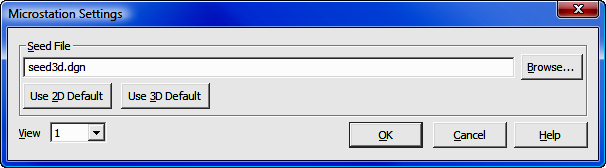
[MicroStation Settings]: Click this button to set the default Seed File to be used when creating a new MicroStation drawing. A seed file may be customized to contain linetypes, layers, symbols, etc.
Seed File: Enter a seed file name or click [Browse] to locate one. You may select a default seed file by clicking [Use 2D Default] or [Use 3D Default]. If you are planning to have any 3D data in your drawing such as contours, select a 3D seed file.
View: This setting defines which view window will be the active view window when MicroStation initializes. Click [q] to select view window 1 through 8.
[OK]: Accept the settings and close the MicroStation Settings dialog box.
[Cancel]: Cancel the seed file selection and close the MicroStation Settings dialog box.
[AutoCAD Settings]: Click this button to set the default Template File to be used when creating a new AutoCAD drawing. A template file may be customized to contain linetypes and layers of which "Sight" Survey can utilize. If you do not want to use a template file, just click [OK] without entering anything in the dialog box.
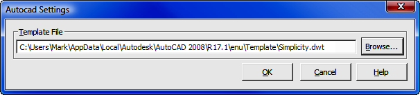
[Browse]: Click the [Browse] button to find a template file. The path shown in the dialog box above is a typical location for AutoCAD drawing files. If you create your own file, you may want to save the template file in a location that is easier to remember.
[OK]: Accept the settings and close the AutoCAD dialog box.
[Cancel]: Cancel the template file selection and close the AutoCAD Settings dialog box.
|
HINT: For information on creating template files, see Section 3.01. |
[IntelliCAD Settings]: Click this button to set certain alias commands.
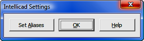
IntelliCAD has established several two-letter aliases which may be issued to call certain CAD routines from the command line. IntelliCAD also has the ability to pass two-letter commands back to "Sight" Survey. Approximately 30 two-letter commands from "Sight" Survey are used for other commands in IntelliCAD. So that you may use the "Sight" Survey commands, clicking the [Set Aliases] button will remap the IntelliCAD commands by simply placing a dash in front of the command. For example: In "Sight" Survey, the command TR is used for traverse. In IntelliCAD, TR is used to issue a trim command. After remapping the aliases, typing TR [Enter] in IntelliCAD will initiate the Traverse routine in 'Sight" Survey. Typing -TR in IntelliCAD will initiate the Trim command.
When you click the [Set Aliases] button you will be asked to confirm your selection.
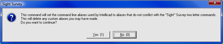
If you choose to continue (by clicking [Yes]) you will then see a warning about writing this new information to your system registry file.
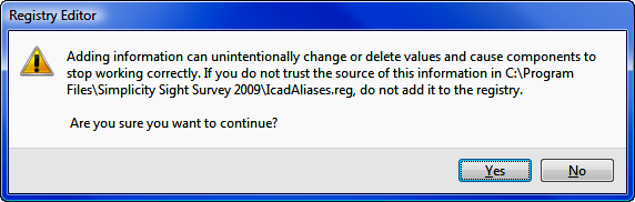
After selecting [Yes] you will see a confirmation window. Once the aliases have been changed you will not need to do this again unless you reinstall "Sight" Survey and/or IntelliCAD.
|
HINT: Before overwriting the aliases, you may want to save a copy of the current alias file in IntelliCAD. There is no need to do this unless you have already customized the alias list in IntelliCAD. To save the current alias list, in Intellicad select Tools > Customize. Select the Aliases tab, then click [Export] and give the file a name. |
Shown below is a listing of the aliases changed by the procedure outlined above. The new alias for each of these commands was produced by adding a dash to the original alias command.
| ICAD Command | New Alias | ICAD Command | New Alias | |
| AREA | -AA | MATCHPROP | -MA | |
| ATTDISP | -AD | OPEN | -OP | |
| APERTURE | -AP | SETESNAP | -ES | |
| ARRAY | -AR | PASTESPEC | -PA | |
| BASE | -BA | POINT | -PO | |
| COPY | -CO | CONFIG | -PR | |
| COPY | -CP | PSPACE | -PS | |
| DIST | -DI | REINIT | -RI | |
| DXFOUT | -DX | SCALE | -SC | |
| FILTER | -FI | FONT | -ST | |
| IDPOINT | -ID | TABLET | -TA | |
| INTERSECT | -IN | TBCONFIG | -TO | |
| ISOPLANE | -IS | TRIM | -TR | |
| LIST | -LI | XREF | -XA | |
| LIST | -LS | INFLINE | -XL |
If you have multiple versions of a CAD application installed on your computer (for example AutoCAD 2006, 2008, & 2009; or MicroStation v8 & PowerDraft) click the [CAD Paths] button to set up the program path to each CAD application. These settings allow you to use any of the installed CAD applications with “Sight” Survey.
|
HINT: If you have only one version of a CAD application, you do not need to set the CAD path. HOWEVER: If you have LDD, AutoCAD Map, or some other flavor of AutoCAD that contains the actual CAD application, use [CAD Paths] to set the correct path. See Using MAP, LDD, etc. below. |
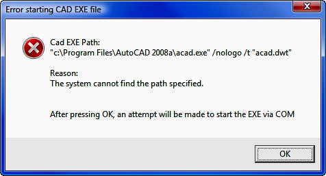
If you start "Sight" Survey and get the following error screen, use [CAD Paths] to set the correct path.
When you click on [CAD Paths] you get this dialog screen:
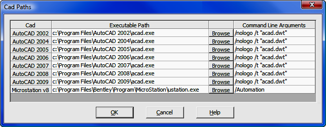
The Cad column contains the versions supported by “Sight” Survey. The Executable Path column contains the actual path to the CAD application. Initially, default values are given. To change a path, click the [Browse] button and use the Windows File Selection dialog to find the correct path. The Command Line Arguments are used by the CAD application at startup. In AutoCAD, the argument /nologo suppresses the application start-up splash screen for faster loading; while the /t “acad.dwt” argument specifies the drawing template used to create a startup drawing. The actual “Sight” Survey drawing uses the template set by the [AutoCAD Settings] button when creating a new drawing. In MicroStation, the /Automation argument suppresses the startup screen and prompt for a drawing name. The command line arguments should not be changed.
You can use enhanced AutoCAD products that contain versions of AutoCAD by setting the CAD path. For example, if you want to use AutoCAD Map 2006, you would select [CAD Paths] then in the AutoCAD 2006 line, click [Browse] and find the location of the acad.exe file under the program folder containing AutoCAD Map. Then in "Sight" Survey you would select AutoCAD 2006 as your CAD program. You must take care to use the same year. In other words, you cannot put information for AutoCAD Map 2006 under the AutoCAD 2004 line.
|
NOTE: "Sight" Survey will not work with any version of AutoCAD LT. |