File Menu
3.01 New Job (NJ)
FUNCTION: The New Job routine is used to close the current "Sight" Survey job and create a new job. Do not use this routine to open an existing job.
Activate the New Job routine by picking from the File menu; by pressing [Alt][F], [N]; or by typing the two-letter command NJ at any data entry prompt.
Job Name: Enter the name of the new job. You do not need to add a filename extension, only the name.
Create Folder for New Job: Checking this box will create a folder of the same name as the Job. While this might sound redundant, keep in mind that "Sight" Survey creates many different files associated with your new job, and by establishing a folder for these files, you are assured that all relevant files are kept in a single location. It is strongly advised that you create a folder for each job by selecting this option.
Location: This setting displays the location of the root folder, the folder in which the new job folder will be created. If you are not creating a new job folder, this is the location where all files associated with the new job will be stored. To change this location, click the [Browse] button.
From this menu you can select the desired root folder or [Make a New Folder]. Normally, "Sight" Survey jobs are kept in a Sight Survey Jobs folder under your Documents folder.
Create New job by importing an old Sight Survey 2 or 3 job: Check this box to import an old Sight Survey job (see Section 2.01).
Distance Unit: Specify the distance unit for this job, either feet or meters.
|
NOTE: US Survey Feet or International Feet? If you have selected Feet as your Distance Unit, you can specify US Survey Feet or International Feet from the Local Configuration menu (LC - Section 5.05). |
Coordinate Format: Select the format for your new coordinate file. You have several choices available: Carlson Numeric; Carlson Alphanumeric; C&G Numeric; C&G Alphanumeric; Sight Survey 3; or LDD (Autodesk Land Desktop). If you are using other software in your office, you might want to select a compatible file format although you will be able to export and import coordinates from any format.
CAD: Select the CAD application you want to use for this job, or select No CAD if you do not want to create a drawing. Choose from AutoCAD (2002-2008); MicroStation v8 (includes v8 XM Edition); Simplicity CAD (IntelliCAD running internally in "Sight" Survey); or AutoCAD Map.
|
TIPS:
|
Open Drawing: Check this setting to open a drawing under the job name.
Enable Raw Storage: Select this option to create a Raw Data file. "Sight" Survey can create an .RW5 raw data file that you can use in the Edit Process Raw routine (ER - Section 11.11) for traverse adjustment.
[File Paths]: This button opens the Project File Manager (FM - Section 3.13) where you can see and/or change the various paths to the Coordinate, Drawing, Raw, and Text Output files.
[OK]: When all your parameters are set to your satisfaction, click the [OK] button to continue.
AutoCAD users: Continue with the AutoCAD Settings section.
MicroStation users: Continue with the MicroStation Settings section.
Template Files: If your CAD application of choice is AutoCAD you are given the option to base your new drawing off an existing Template File. A template file may be customized to contain linetypes and layers of which "Sight" Survey can utilize. If you do not want to use a template file, just click [OK] without entering anything in the dialog box.
[Browse]: Click the [Browse] button to find a template file. The path shown in the dialog box above is a typical location for AutoCAD drawing files. If you create your own file, you may want to save the template file in a location that is easier to remember.
[OK]: Accepts the settings and continues to load AutoCAD.
[Cancel]: Cancels the template file selection, but continues to open AutoCAD using default settings.
|
CREATE A TEMPLATE FILE: Since "Sight" Survey will only use linetypes that already exist in a drawing, you may want to create a template file containing commonly used linetypes. (Layers are not an issue since "Sight" Survey can create them as they are needed.) To create a template file:
|
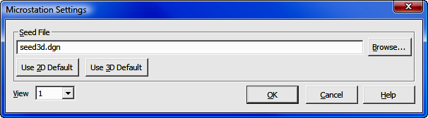
Seed Files: If your CAD application of choice is MicroStation you are given the option to base your new drawing off an existing Seed File. A seed file may be customized to contain linetypes, layers, symbols, etc.
Seed File: Enter a seed file name or click [Browse] to locate one. You may select a default seed file by clicking [Use 2D Default] or [Use 3D Default]. If you are planning to have any 3D data in your drawing such as contours, select a 3D seed file.
View: This setting defines which view window will be the active view window when MicroStation initializes. Click [q] to select view window 1 through 8.
[OK]: Accepts the settings and continues to load MicroStation.
[Cancel]: Cancels the seed file selection, but continues to open MicroStation using default settings.