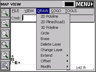
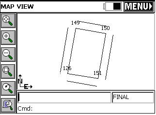
The Draw menu is found next to the View menu in MAP view. Below you will find each feature described.
2D Polyline (PL) (AutoCAD style):
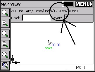
This command allows you to draw a polyline between points. You can pick points from the screen or type in point numbers. First, pick your starting point then you have several options on the command line. The default option is to keep picking points and the other options are described below.
Cmd:Polyline-Arc/Close/Undo/<End>
A: Starts an arc segment. See below for details.
C: Closes the polyline (you must have at least two polyline segments drawn before you can close)
U: Will undo the last segment drawn.
E: Will end the Polyline command.
Constructing an arc segment
After choosing A, the command line will change to:
Cmd: Polyline-Arc CEn/LEn/SEc/<RAd>
You have various options for constructing an arc as part of your polyline.
CEn: Allows you to specify the center point (or radius point) for the arc. After picking the center point, you must specify the arc end point and then the arc direction.
LEn: Allows you to specify the arc length. First you pick the arc end point and then you can enter the arc length. The minimum arc length is given to you.
SEc: Allows you to specify the second point and end point to define the arc.
RAd: Allows you to specify a radius length. First you pick the arc end point and then you can enter the radius length. The minimum radius length is given to you.
2D Polyline (Road) (2DP):
This command allows you to draw a 2D Polyline. This command is similar to the polyline command described above with the following additions:
+/-: The +/- options activate an additional prompt that allows you to plot line segments at a 90 degree deflection angle from the last line. [+] is a right deflection and [–] is a left deflection.
Len: This option prompts you for the length of a line segment. Enter the length and a line segment will be drawn that length using the same bearing as the previous line segment. If the previous segment is an arc, then the new segment will be tangent to that arc.
3D Polyline (3DP):
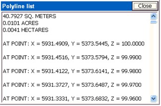
The 3D Polyline command is similar to the 2D polyline command. It will even draw arcs, but will create a polyline on the screen with many vertices at different Z elevations which are linearly interpolated around the arc. If the start of the arc is point 17 at elevation 100 and the end of the arc is point 9 at elevation 90, then using View, List, you would see intermediate vertices (note that the segment length between vertices is about 0.05 units).
If you select 3D Polyline but pick points that are all at 0 elevation, you will create a 2D polyline.
Circle (CR):
This command draws a circle entity, based on diameter defined by two points or based on a center point and a radius.
Erase (E):
Erases all selected polylines. It will not erase points. Note that you can erase an entire area by drawing a Window through the polylines (picking first a lower left point in “blank space”, then picking an upper right point). If you even contact or enclose any polylines with this window selection, they will be erased. So the “window” erase procedure mimics the “crossing” selection method of AutoCAD.
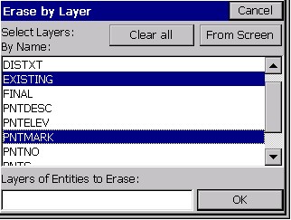
Delete Layer (DL):
Select from a list one or more layers, then the routine will delete all the polylines on those layers.
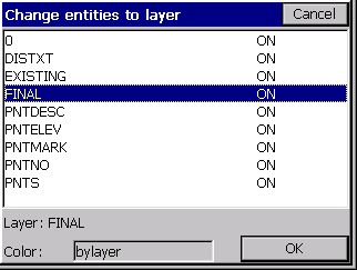
Change Layer (CHG):
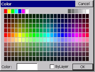
This changes the layer of the selected polylines. One form of selection is to type L and press Enter in order to select last created polyline from the drawing. The routine displays the "Change entities to layer" dialog box. When the dialog appears on the screen, the selection in the layer list will be set to the current layer. Clicking the color bar brings up the color palette, letting you change the color by picking or ByLayer.
Offset - 2D (O2):
Mimics the AutoCAD Offset command, and only works with 2D polylines. Enter the offset distance and pick the left or right offset amount.
Offset - 3D (O3):
This offsets 3D polylines both horizontally and vertically. It is great in combination with road/utility centerlines to create offset polylines to stake. If you do the “segment” option versus the “continuous” option, it will break the corners and offset the projection of the line. This creates vertices that can be turned into points using the command P2P, and is useful for building offsets.
Modify - Remove Arcs (RMA):
Pick any polyline with an arc, specify the “offset cutoff” spacing, and turn the arc into chords. Offset cutoff refers to the maximum separation between the chord and the original arc. If you enter a small cutoff distance of 0.1, then at no point do the chord segments differ from the arc than 0.1. Be careful with this command – there is no “Undo” to restore the arcs (though you can immediately start a new job and “re-load” the last, saved DXF file of the drawing).
Modify - Fillet (F):
Similar to AutoCAD’s Fillet command. It prompts: Cmd: Fillet -Ra/Pl/eXit/First seg 25.00. If you are trying to inscribe a curve at the corner of a polyline, you enter the desired radius first (at the above prompt). Then you choose the P option. This leads to the prompt, Cmd: Fillet -Ra/Pl/eXit/Select pl 25.00. Select the polyline near the vertice where you want the curve to go. This completes the process. If you wish to change the radius, enter R. If you want to fillet the corner of 2 distinct polylines, then just pick them as prompted (do not do the P for Polyline option). This command will only work with 2D polylines, completed with the command 2DP, or imported from a DXF file as 2D polylines, or converted from 3D using the command C2D.
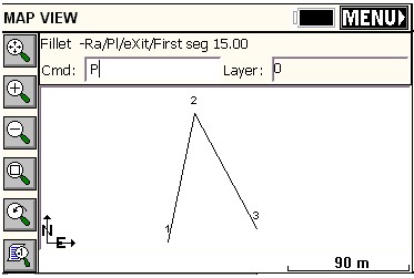
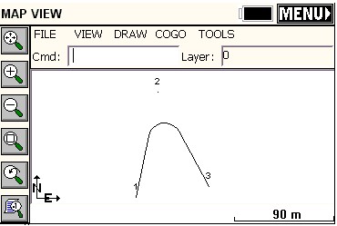
See the above two figures. Because in the top figure, from 1 to 2 to 3 was one continuous polyline, after the radius was set at 15, P was entered to set up the one-pick approach for polylines, leading to the completed fillet command and the result as shown in the bottom figure. Now you can do Cogo, Interpolate Points, Polylines to Points (P2P) and solve for the points for the beginning of the arc, radius and end of arc, for purposes of stakeout (set out).
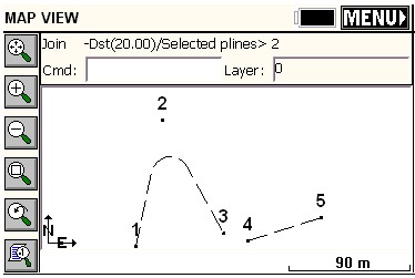
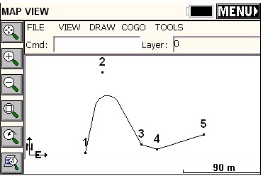
Modify - Join (JN):
This command allows you to join polylines. Enter D to specify a new maximum separation distance, then select the polylines on the MAP screen. The advantage of joining polylines is that they can then be offset as a unit, and the vertices of the offset polylines can be turned into points for stake out. The offset command, in effect, does all the complicated bearing-bearing intersects for you. For example, if the resulting polyline were a pipeline with a 20 meter total right-of-way, then to stake the right-of-way points, you would offset the polyline 10 units left, then 10 units right, then turn both offset polylines into points.
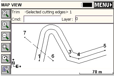
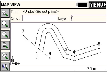
Modify - Trim (TM):
This allows you to trim polylines to the edge of other polylines just like in AutoCAD. Then the command Polyline to Points (P2P) will make turn all vertices, including the trimmed end points, into points for stakeout.
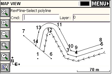
Modify - Reverse Polyline (RV):
When you turn a polyline into points, it will start the point numbering at the beginning of the polyline. Thus it may be useful to control the direction of the polylines. This is done with the command Reverse Polyline. Each time you pick a polyline using this command, you reverse its direction, and little temporary arrows are displayed along the polyline indicating the current direction. If it is not the direction you want, reverse again.