Curves Menu
8.11 Traverse Arc with Offset (AO)
FUNCTION: The Traverse Arc with Offset routine is used to compute the coordinates of a point lying along an arc when given the coordinates of the point of curvature, the coordinates of the center point of the arc and one other of the following four parameters: the arc length; the chord length; the tangent length; or the central angle (delta) of the arc. This routine will also set offset points at the curve end point.
Activate the Traverse Arc with Offset routine by picking from the Curves menu; by pressing [Alt][V], [A], or by typing command AO at any data entry prompt.
BS Point: This is an informational field showing you the backsight point. You cannot enter data into this field. To change the backsight point, use the Enter Backsight Point routine by typing EP in any data entry box (see Section 6.07).
BS Bearing: This is an informational field showing you the backsight bearing. You cannot enter data into this field. To change the backsight bearing, use the Enter Backsight Bearing routine by typing EB in any data entry box (see Section 6.08).
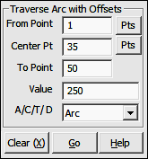
From Point: This is the currently occupied point, which is also the PC. If you have an occupied point this box will automatically be filled for you. Changing the From Point is equivalent to running the Go To routine (GT - Section 6.06), and will change the BS Bearing.
|
|
TIP: Left-click the [Pts] button to select a point from the Point Manager (see Section 6.09). Right-click the [Pts] button to select a point from the CAD window (see Picking Points in CAD in Section 2.03). |
Center Point: Enter the number of the center point of the arc.
|
|
TIP: Left-click the [Pts] button to select a point from the Point Manager (see Section 6.09). Right-click the [Pts] button to select a point from the CAD window (see Picking Points in CAD in Section 2.03). |
To Point: Enter the number of the point you which you are traversing, the point you want to establish.
Value: Enter the known item of data, (Arc, Chord, Tangent or Delta). The numeric sign of the data entered determines the direction to be traversed. If you are traversing in a CLOCKWISE direction, enter your data as POSITIVE value. Use a NEGATIVE value if you are traversing COUNTER-CLOCKWISE.
A/C/T/D: Indicate the nature of the value you entered at the Value prompt. Press [A] if the value was an Arc length; [C] if the value was a Chord length; [T] if the value was a Tangent length; or [D] if the value was a Delta angle.
"Sight" Survey will compute and print to the Text Output window the coordinates for the new PT point, print the Central Angle, Radius, Arc, and Tangent Length, Chord and Chord Bearing from PC to the PT.
At this point, two events have occurred. The PT has become the currently occupied point, which is also the new PC should you continue to traverse along the arc. Also, the bearing from the PT back to the Center Point is now the reference bearing, if one is needed for the next calculation. Therefore, to proceed away from the PT tangent to the traversed arc, you would enter the Traverse routine (TR - Section 7.09) and input an angle of 90 degrees (or 100 grads) AR or AL as the case may be.
If an Offset Table has been defined (OD - Section 6.21) "Sight" Survey will place points at the offsets enumerated in the table. If Automatic Point Numbering (AN - Section 2.10) has been turned on, the computation is fully automatic. If you are manually numbering your points, you will be prompted for each point number until all the table values have been exhausted.
|
|
TIP: To use the next available point number, just press [+] instead of entering a number. |
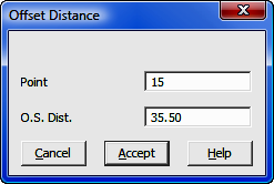
After setting the predefined offset points, or if there are no predefined offsets, you may enter individual offsets through this dialog box:
Point: Enter a number for the offset point or press [+] for the next unused point number. If Automatic Point Numbering (AN - Section 2.10) has been turned on you will only need to enter an offset distance.
O.S. Dist: Enter a positive distance value to offset to the right with respect to the foresight direction. Likewise, enter a negative distance value to offset to the left with respect to the foresight direction. To exit the offset entry, simply click [Cancel] or leave the O.S. Dist. field blank and press [Enter].