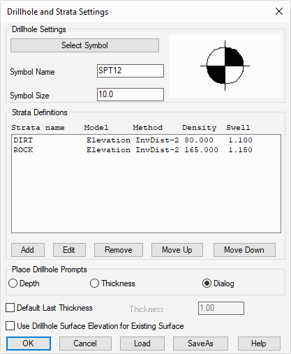
For this tutorial, we are interested in rock quantities and we need to define two strata:
- DIRT (material above the rock), and,
- ROCK
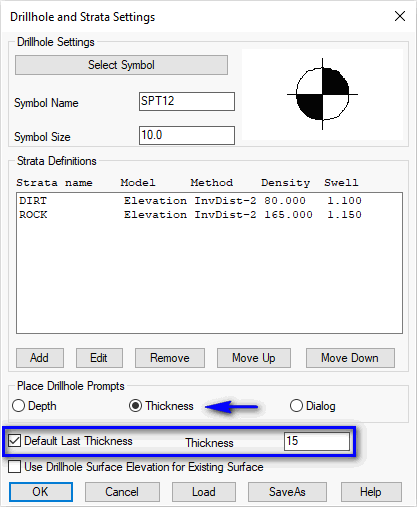
Next, pick the Add button again. This time, fill out the dialog with a strata name of "ROCK" and use the information below to add the second strata material into the project and click OK when complete:
| Values | Strata 1 | Strata 2 |
|---|---|---|
| Name | DIRT | ROCK |
| Density | 80 | 165 |
| Swell Factor | 1.10 | 1.15 |
| Model Values | By Elevation | By Elevation |
| Modeling Method | Inverse Distance - Power 2 | Inverse Distance - Power 2 |
- Inverse Distance will not carry trends and the
calculated strata model will never be higher or lower than the
original drillhole data and uses a weighted average of the
drillhole data. In general, closer drillholes are weighted more
than drillhole farther away:
- Inverse Distance - Power 2 will weigh drillholes more that are further away.
- Inverse Distance - Power 3 will weigh drillholes less that are further away.
- Linear Least Squares extrapolates trends and allows for a strata model to create new highs and lows that don't appear in the original drillhole data.
- Drillhole Import which reads the drillhole data from a text file. This command supports customizing the sequence of drillhole data fields to match the format of the text file. This process is discussed in the GeoTech Reports tutorial.
- Place Drillhole creates the drillholes at picked positions in the drawing and enters the data in a dialog.
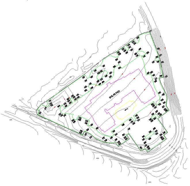
Station/<Pick Drillhole Location>: pick a location northeast of the building pad as shown below:
 A dialog box
similar to that shown below appears. The Surface Elevation
is automatically filled in using the
Existing Ground Surface. The Drillhole Name, Water
Table Elevation and Description are optional. The
list of strata defaults to the strata defined in
Drillhole/Strata Settings. Each strata defaults to
a thickness of zero.
A dialog box
similar to that shown below appears. The Surface Elevation
is automatically filled in using the
Existing Ground Surface. The Drillhole Name, Water
Table Elevation and Description are optional. The
list of strata defaults to the strata defined in
Drillhole/Strata Settings. Each strata defaults to
a thickness of zero.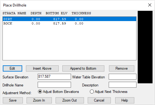
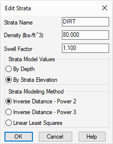
Select/Highlight the DIRT entry and click the Edit button to display a secondary dialog box similar to that shown below:
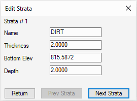
For this location, indicate the DIRT strata has a Thickness of 2 (press the Tab key to see the updated values) and then click Next Strata.
For this example, we only know the depth to the top of rock depth and not the total rock thickness. We will treat all cut below the top of rock as ROCK strata. So we'll set the rock thickness deep enough to be lower than the Maximum Cut on site. In this case, indicate the ROCK strata has a Thickness of 15 (press the Tab key to see the updated values and then click Return to display a dialog box similar to that shown below:
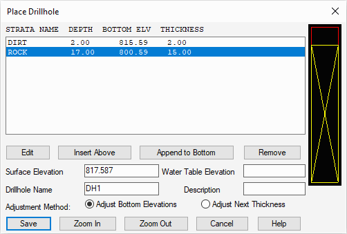
Complete the remaining values as desired and click Save. When prompted:
Pick Drillhole Location (Enter to end): press Enter
NOTE: If you had known the coordinates for the drillhole, you can type in the Easting,Northing format instead of picking on the screen.
Now let's locate two more drillholes using a different method. Return to the Define Drillhole and Strata Settings command and set the changes as illustrated below and click OK when ready:
Re-issue the Place Drillhole again and when prompted:
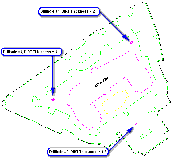
Station/<Pick Drillhole Location>: pick a position in the lower parking lot
Strata DIRT Thickness: type 1.5 and press Enter (complete any remaining items for DH2 and click Save)
Pick Drillhole Location (Enter to end): pick a position left of the main building
Strata DIRT Thickness: type 3 and press Enter (complete any remaining items for DH3 and click Save)
Pick Drillhole Location (Enter to end): press Enter
Now that the drillholes are in the drawing, we can explore the creation of sub-surface stata models.
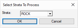
Select Strata to Process: indicate the ROCK surface as illustrated below:
Select point for color legend (Enter for None): pick a location of your choosing (top center of the legend)
Legend size <10.0>: press Enter
Label all zones or summary [All/<Summary>]? press Enter
This command compares the design surface with the strata surface to make a cut color map of the cut depths for the strata. This command is one way to verify that the strata surfaces are modeled correctly. The result should be similar to that shown below:
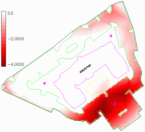
Optional: Remove the Strata Cut Color Map through the StrataCalc -- Erase Strata Cut Color Map command.
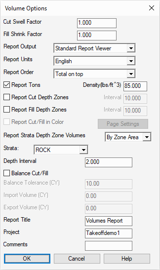
When strata surfaces are defined, the volume routine will separate the cut volume into the different strata. Depth Zones (2 ft zones in this case) can also be defined in this command. Set the values as shown above and click OK when ready. The resulting dirt and rock quantities are summarized in a report similar to that shown below:
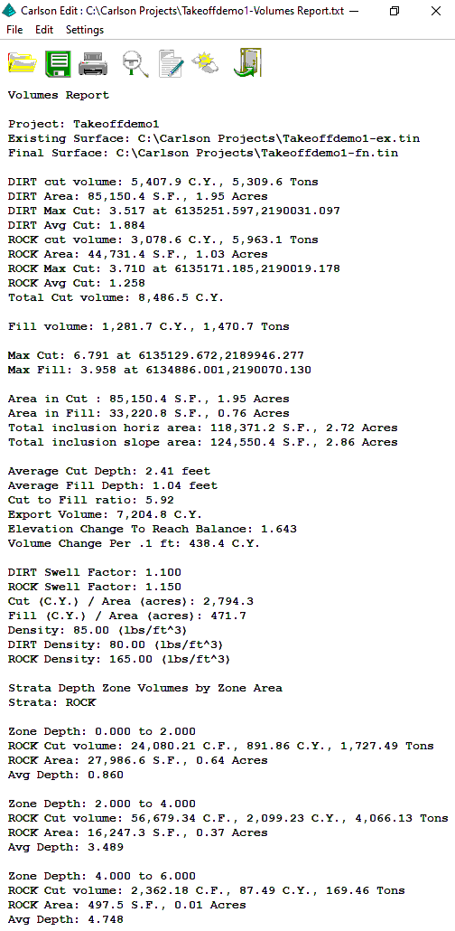
Review and click the Exit (Doorway) button when complete.