- If you get the Start Page, pick Open Files.
- If you get the Startup Wizard dialog box, click the Browse button.
- If you are taken directly into CAD, click File -- Open.
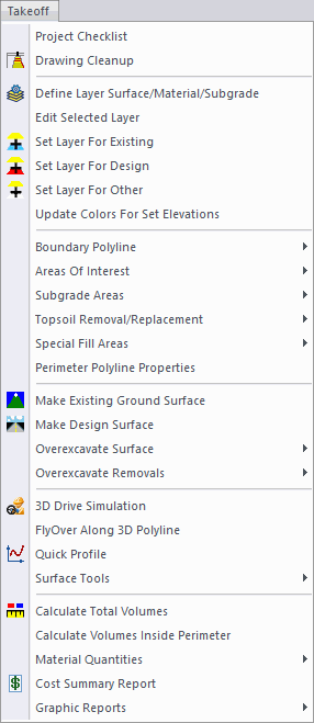
Many of these commands are also grouped as icons in the Takeoff General toolbar shown here:

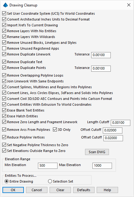
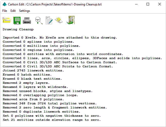
This command will apply the selected cleanup function(s) on the drawing to help automate the cleanup. Here's a brief description of the most important of these functions:
- Remove Layers With No Entities: Drawings often have lots of layers. This routine removes layers that have no entities in the drawing so that we don't have to deal with them.
- Join Linework With Same Endpoints: This routine will take linework that is broken into multiple segments and join them into a single linework entity. For example, it will join together broken segments of a contour polyline into a single polyline.
- Reduce Polyline Vertices: This routine removes extra vertices from polylines as long as the removing does not shift the polyline more than the specified Offset Cutoff distance. This will reduce the size and complexity of the drawing.
- Set Elevation Outside Range To Zero: In case the drawing contains entities that are outside the range of valid elevations for the site, this routine will set them to zero elevation. The program treats zero elevations as "no elevation" and modeling will filter out these zero elevation entities.
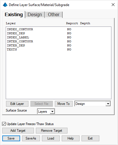
- Existing - Used to model initial/pre-construction site conditions.
- Design - Used to model proposed/post-construction site conditions.
- Other - Used as a collection of unknown/irrelevant site conditions (text notes, hatches, etc).
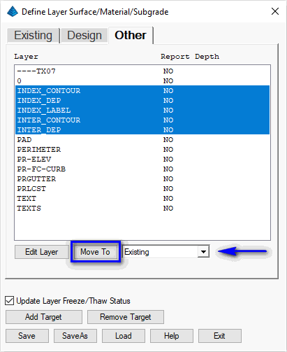
To switch between lists, pick the tabs at the top of the dialog. In this drawing, all the contours are for the existing ground surface. In the layer list, all the layers that start with INDEX and INTER are for these existing ground contours. Select/highlight these layers and then click the Move To button with the Existing target as shown above (to highlight multiple layers at a time use standard Windows Ctrl+click and/or Shift+click functionality.
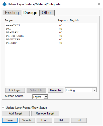
Next move the layer names that start with PR (for proposed) to the Design target by highlighting these layers and clicking Move To with the Design target selected. Also move the layer PAD to Design. Finish by clicking the Save button to save the changes and then pick Exit.
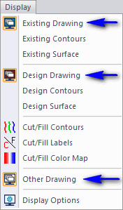
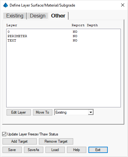
Practice turning on/off the Existing Drawing, Design Drawing and Other Drawing. When only Existing Drawing is on, you should see just the contours. When only Design Drawing is on, you should see just the design polylines and leader labels. When only Other Drawing is on, you should see the entities that are assigned to neither Existing nor Design. Set this condition as active:
- Existing is Off
- Design is Off
- Other is On
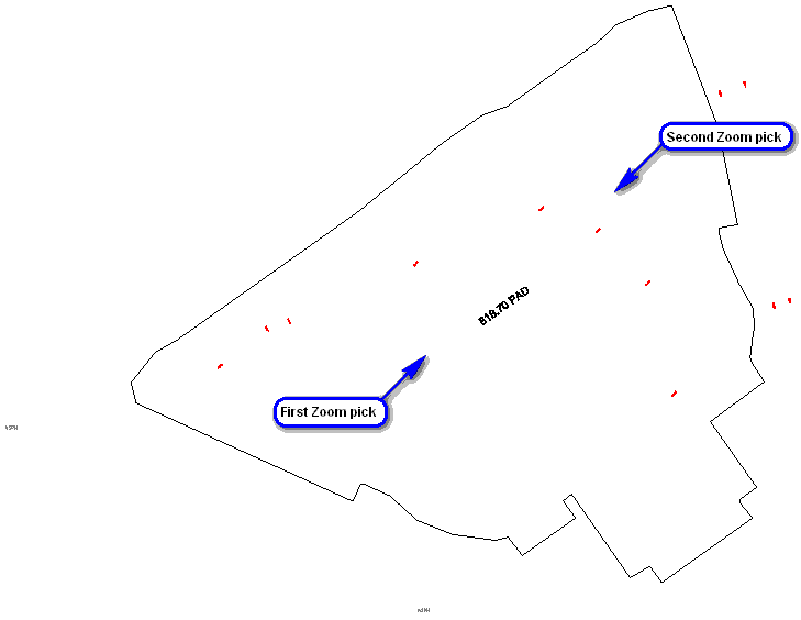
Some of these layers we do want to assign to the Existing and Design targets. To better see the entities, use the View -- Window command and pick two points that make a window around the entities as shown above. Once zoomed in, you can see a text label of 818.70 PAD which is for the Design target. Other labels 817.00, 818.00, etc, are contour labels for the Existing contours. There are a few commands in the Inquiry menu to find out the layer names for these entities and two quick ones are:
- List
- Layer ID
Pick entity to read layer: pick the 818.70 PAD label (the entity is reported as being on the ----TX07 layer)
Pick entity to read layer: pick the 818.00 label (the entity is reported as being on the TEXTS layer)
Pick entity to read layer: press Enter
With this information known, we could return to the Define Layer Surface/Material/Subgrade but let's explore the use of organizing the data through a visual screen-pick. Issue the Takeoff -- Set Layer for Design command and when prompted:
Select entities for design surface.
[FILter]/<Select entities>: pick the 818.70 PAD label
[FILter]/<Select entities>: press Enter
The layer of the selected entity is migrated to the Design classification and its visibility set consistent with that target. Issue the Takeoff -- Set Layer for Existing command and when prompted:
Select entities for existing surface.
[FILter]/<Select entities>: pick the 818.00 label
[FILter]/<Select entities>: press Enter
The layer of the selected entity is migrated to the Existing classification and its visibility set consistent with that target.
NOTE: To short-cut these commands, explore the use of the Takeoff/SiteNET Display toolbar as shown below:

With this work complete, we can return the drawing view back by running View -- Extents command. Let's validate our layer classifications. Re-issue the Takeoff -- Define Layer Surface/Material/Subgrade command and visit each tab to the values suggested below:
| Existing Layer Targets | Design Layer Targets | Other Layer Targets |
|---|---|---|
|
|
|
- Existing is Off
- Design is On
- Other is Off
Pick entity to read layer: pick the large pad polyline (it reports the PAD layer)
Pick entity to read layer: pick the curb polyline (it reports the PR-FC-CURB layer)
Pick entity to read layer: press Enter
Next we need to make sure that these polylines are closed. In this example, the outside curb polyline is open at the top. To close the polylines, run Edit -- Polyline Utilities -- Edit Polyline -- Close Polylines and when prompted:
Select Polylines to set closed.
[FILter]/<Select entities>: pick each of the pad and curb polylines (six in all) and press Enter when done selecting
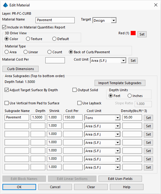
Re-issue the Takeoff -- Define Layer Target/Material/Subgrade command and activate the Design tab. Select/activate the PAD layer and click the Edit Layer button. A dialog appears for defining the Pad material properties. Set the values as shown below and click OK when ready:
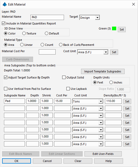
NOTE: Calculating cost is an optional feature. For this example, we cited a Cost of "$15" per "Ton" with a density of "110."
Next pick layer PR-FC-CURB and choose Edit Layer. Set the values as shown below and click OK when ready:
Review the summary depths of the pay materials we just modified. Click the Exit button and indicate Yes to save changes.
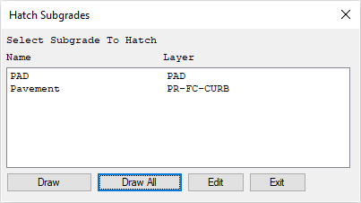
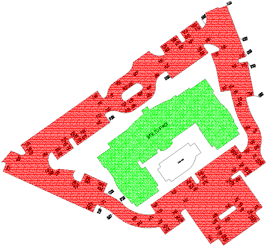
Click the Draw All button. The resulting hatch areas show where the subgrade is applied. Notice how the islands are not hatched because they are curb polylines that are already inside another curb polyline. Also note that the smaller pad area is not hatched because this polyline layer is different from the bigger pad polyline.
Optional: Re-run the Hatch Subgrade Areas command, select a desired subgrade layer and click the Edit and attempt to match the look of the image below through the following settings:
| Subgrade | Hatch Pattern | Color |
|---|---|---|
| PAD | Conc | Green |
| Pavement | Asphalt | Red |
 When finished
viewing the subgrade areas, issue the Takeoff -- Subgrade Areas --
Erase Subgrade Hatches command.
When finished
viewing the subgrade areas, issue the Takeoff -- Subgrade Areas --
Erase Subgrade Hatches command.Let's start by working on the Existing surface. To isolate the existing entities, use the Takeoff -- Display menu commands to set this condition as active:
- Existing is On
- Design is Off
- Other is Off

In this example, the existing ground surface is defined by just contour polylines and these polylines already have elevation. So there are no changes needed for preparing the existing surface entities. If the contour polylines were at zero elevation, then you could use the Elevate -- Assign Contour Elevation menu commands (such as Multiple in Series).
- Existing is Off
- Design is On
- Other is Off
List Elevation [Options/<Select Entity>]: pick the main pad polyline (its elevation of 0 is confirmed)
Select Entity (Enter to end): press Enter
To set the pad polyline elevation, run the Elevate -- Set Polyline To Elevation command and when prompted:
Enter/<Select text or linework of elevation>: pick the 818.70 PAD text (the non-numerical information is stripped and the numeric value is reported)
Enter elevation to add to text values <0.0>: press Enter
Select entities for elevation change.
[FILter]/<Select entities>: pick the larger pad polyline
[FILter]/<Select entities>: press Enter
Next, let's set the elevation of the smaller pad under the main pad. Use the View -- Window command to zoom in around the smaller pad so that we can read the text label. The label of 17.56 is short for 817.56. In this example, the 800 was dropped from many of the elevation labels to save on label clutter. Run the Set Polyline To Elevation again. This time when prompted:
Enter/<Select text or linework of elevation>: pick the 17.56 text (any non-numerical information is stripped and the numeric value is reported)
Enter elevation to add to text values <0.0>: type 800 and press Enter
Select entities for elevation change.
[FILter]/<Select entities>: pick the smaller pad polyline
[FILter]/<Select entities>: press Enter
Then run View -- Zoom -- Previous (keyin short-cut ZP to get back to the full view of the site (color changed for clarity):
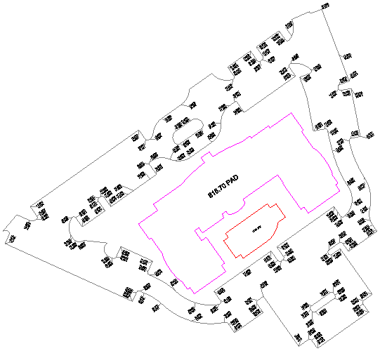
Finally, we need to set the elevations for the curb polylines. First, use the View -- Window to zoom in around some of the curb labels below the smaller pad as illustrated below:
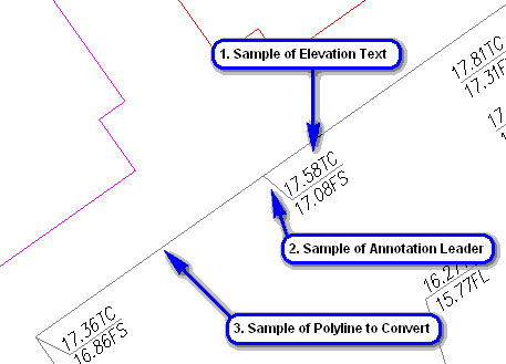
Next, issue the Elevate -- 2D to 3D Polyline -- Text With Leader command. This command will assign the elevations from the labels to the polylines by following the label leader to find the position on the polyline. For polyline vertices without elevation labels, the elevations will be interpolated from the other labels. When prompted:
Options/Select sample of elevation text: pick one of the labels with a "TC" suffix as cited in item 1 above and press Enter
Select sample of an annotation leader: pick the associated leader line as cited in item 2 above and press Enter
Select sample of a polyline to convert: select a sample of a polyline for conversion as cited in item 3 above and press Enter
Select polylines to convert, leaders and elevation labels to process.
[FILter]/<Select entities>: type all and press Enter twice
Enter elevation to add to label values <0.00>: type 800 above and press Enter
Next, a dialog appears for selecting which label names to use:
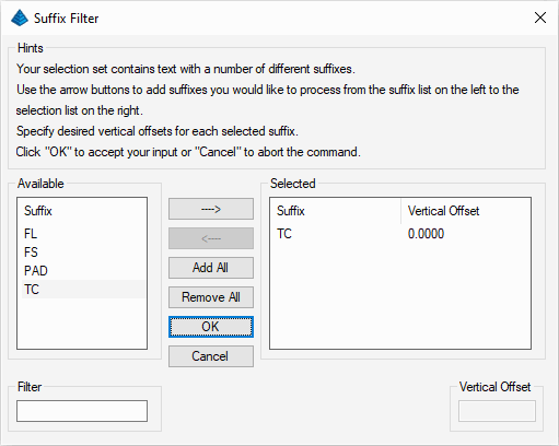 When Takeoff detects different text
labels within the elevation labels, you need to choose which ones
to process. In this case, we only want the labels with TC
(Top of Curb), so highlight TC and click the
---> (Add) button and then click
OK when ready. All the curb polylines now have
elevations and should also have colors because the elevations are
assigned. Finally, issue the View -- Extents to
return to the full site view.
When Takeoff detects different text
labels within the elevation labels, you need to choose which ones
to process. In this case, we only want the labels with TC
(Top of Curb), so highlight TC and click the
---> (Add) button and then click
OK when ready. All the curb polylines now have
elevations and should also have colors because the elevations are
assigned. Finally, issue the View -- Extents to
return to the full site view.- Existing is Off
- Design is On
- Other is On
Select boundary polylines.
[FILter]/<Select entities>: pick the perimeter polyline as shown below:
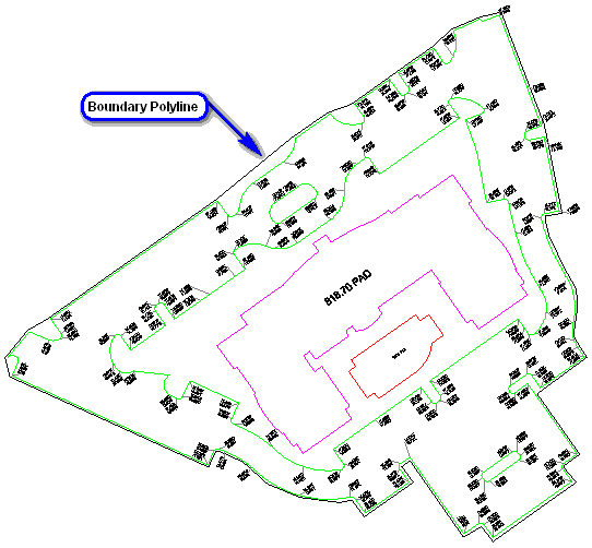
This selected polyline is now set as the boundary polyline for the rest of the Takeoff routines.
- existing ground, and,
- design considerations
- To make the Existing Ground surface, issue the Takeoff -- Make Existing Ground Surface. The program will process the entities (regardless of their screen visibility) and make the triangulation surface.
- To make the Design Ground surface, issue the Takeoff -- Make Design Surface.
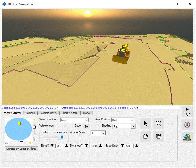
This routine shows a 3D view of the site and allows you to "drive" around through the use of the arrow keys on most standard keyboards. This is a good way to check that the surface triangulated correctly. We want to make sure that there are no elevation spikes and that the subgrade depths are modeled. To drive the site:
- choose a View Direction, and,
- choose a View Position, and,
- choose a Vehicle, and,
- choose a Speed
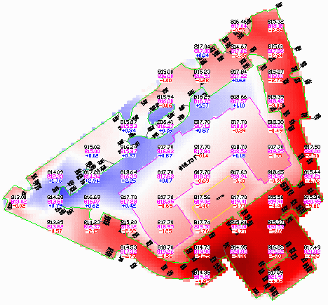
Under default conditions:
- Cut areas are drawn in different shades of red (deeper colors represent deeper cut), and,
- Fill areas are drawn in blue, and,
- regions in Cut/Fill neutral areas tend to shade white
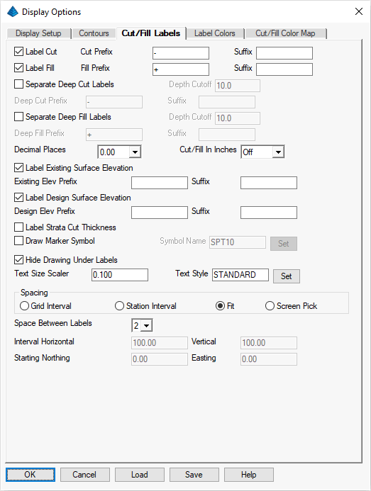
The resolution of the color blocks in the map can be changed through the Spacing group of controls. Turn off the Cut/Fill Labels by re-issuing the Display -- Cut/Fill Labels command to uncheck it.
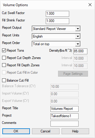
The settings the Cut Swell and Fill Shrink factors get multiplied into the cut/fill volumes. Set these factors as desired and click OK when ready. The results are displayed similar to that shown below:
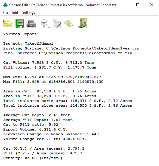
Click the Exit (doorway) icon when ready. Run the command again and change the Report Output mode to see the volumes in different formats like PDF or Excel.
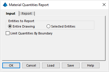
Specify the options as shown above (feel free to explore the options in the Report tab) and click OK when ready. The report includes (among other this) the:
- Count, and,
- Length, and,
- Area, and,
- Volume
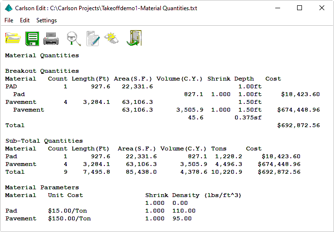
Click the Exit (doorway) icon when ready. The Takeoff -- Material Quantities -- Custom Report command can be used to report these values with control of the report format and the option to export to Excel.
Review and set the values as suggested above and click OK when ready to display a dialog box similar to that shown below:

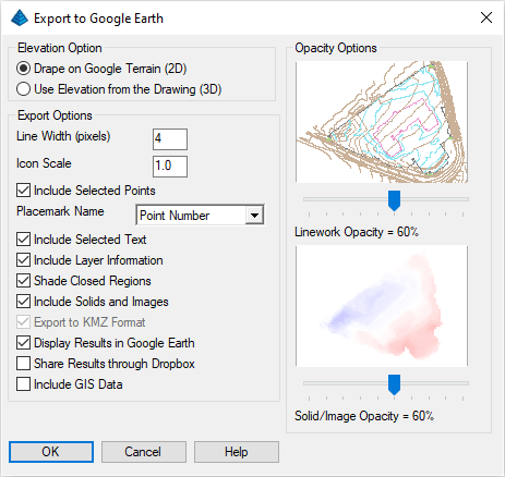
Provide the file name specified above and click the Save button when ready. When prompted:
Select points, polylines, text, solids, images, lines and arcs to write.
[FILter]/<Select entities>: type all and press Enter twice
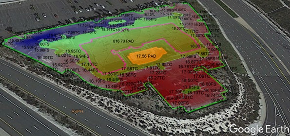
The results are overlaid on Google Earth as illustrated below: