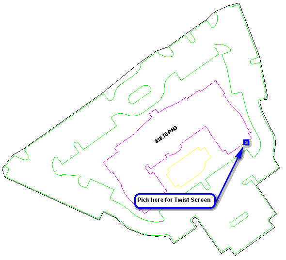
Next, let's orient the drawing so that the building better aligns with the screen. Issue the View -- Twist Screen -- Line, Polyline or Text command. When prompted:
Pick a line, polyline or text: pick on the northeast end of one of the building as shown above
Twist azimuth for selected LWPOLYLINE (Use 90 for Due East) <90.0>: press Enter
The drawing view is changed (and the coordinates remain as-is).
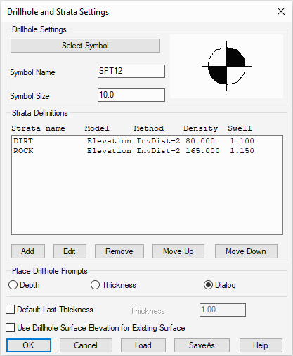
For this tutorial, we need to define two strata:
- DIRT (material above the rock), and,
- ROCK
Next, pick the Add button again. This time, fill out the dialog with a strata name of "ROCK" and use the information below to add the second strata material into the project and click OK when complete:
| Values | Strata 1 | Strata 2 |
|---|---|---|
| Name | CLAY | LIMESTONE |
| Density | 80 | 165 |
| Swell Factor | 1.10 | 1.15 |
| Model Values | By Elevation | By Elevation |
| Modeling Method | Inverse Distance - Power 2 | Inverse Distance - Power 2 |
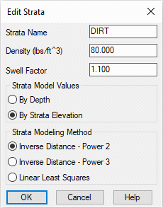
- Inverse Distance will not carry trends and the
calculated strata model will never be higher or lower than the
original drillhole data and uses a weighted average of the
drillhole data. In general, closer drillholes are weighted more
than drillhole farther away:
- Inverse Distance - Power 2 will weigh drillholes more that are further away.
- Inverse Distance - Power 3 will weigh drillholes less that are further away.
- Linear Least Squares extrapolates trends and allows for a strata model to create new highs and lows that don't appear in the original drillhole data.
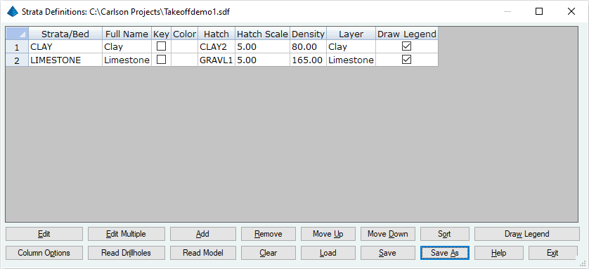
Click Add and fill out the data as shown below and click OK when ready:
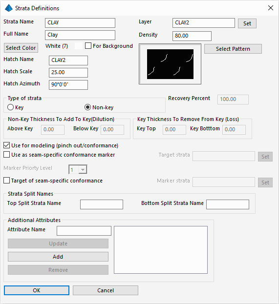
Use the table below for the specific values:
| Values | Strata 1 | Strata 2 |
|---|---|---|
| Strata Name | CLAY | LIMESTONE |
| Full Name | Clay | Limestone |
| Layer | Clay | Limestone |
| Density | 80 | 165 |
| Hatch Name | CLAY2 | GRAVL1 |
| Hatch Scale | 5.00 | 5.00 |
| Hatch Azimuth | 90°0'00" | 90°0'00" |
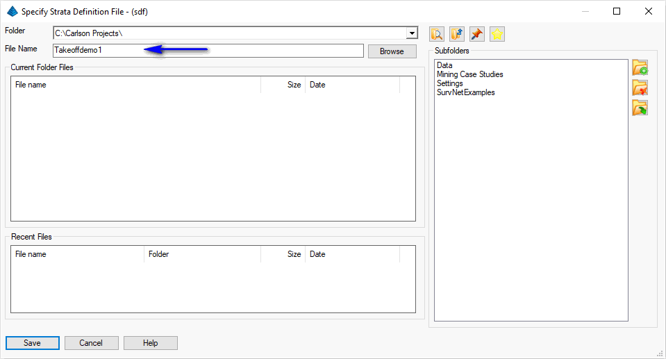
Supply the name as shown above and click Save when ready. Finally, click the Exit button to dismiss the Define Strata/Bed dialog box.
- Drillhole Import which reads the drillhole data from a text file. This command supports customizing the sequence of drillhole data fields to match the format of the text file.
- Place Drillhole creates the drillholes at picked positions in the drawing and enters the data in a dialog. This process is discussed in the Takeoff Drillholes and Strata tutorial.
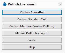
Choose the Custom Formatter option. When prompted:
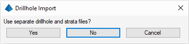
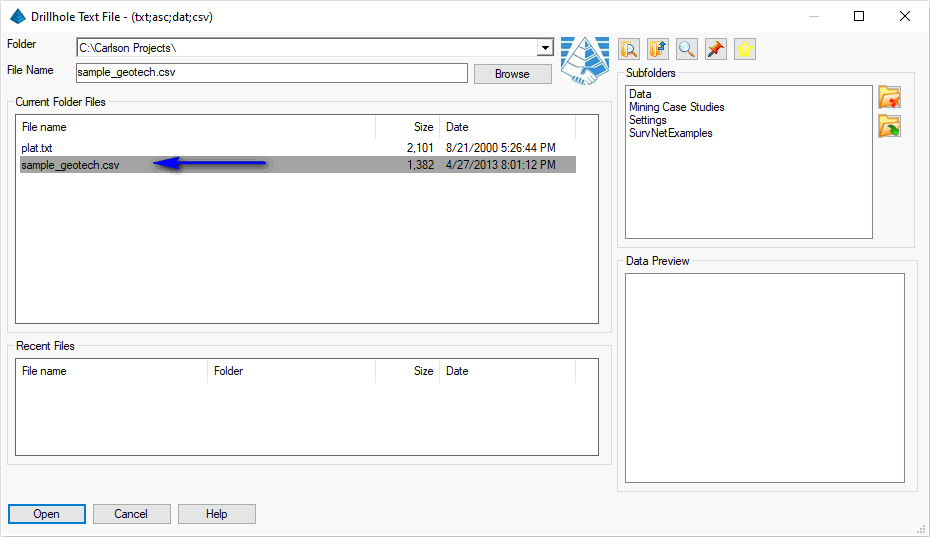
Indicate No as both the drillhole and strata data are stored in the same file. For the Drillhole Text File, specify the file shown below and click Open when ready:
NOTE: The file contains fields of data in the following order:
- DRILLHOLE
- NORTH
- EAST
- SURFACE
- STRATA
- BOTDEPTH
- MOISTURE
- PLASTICITY
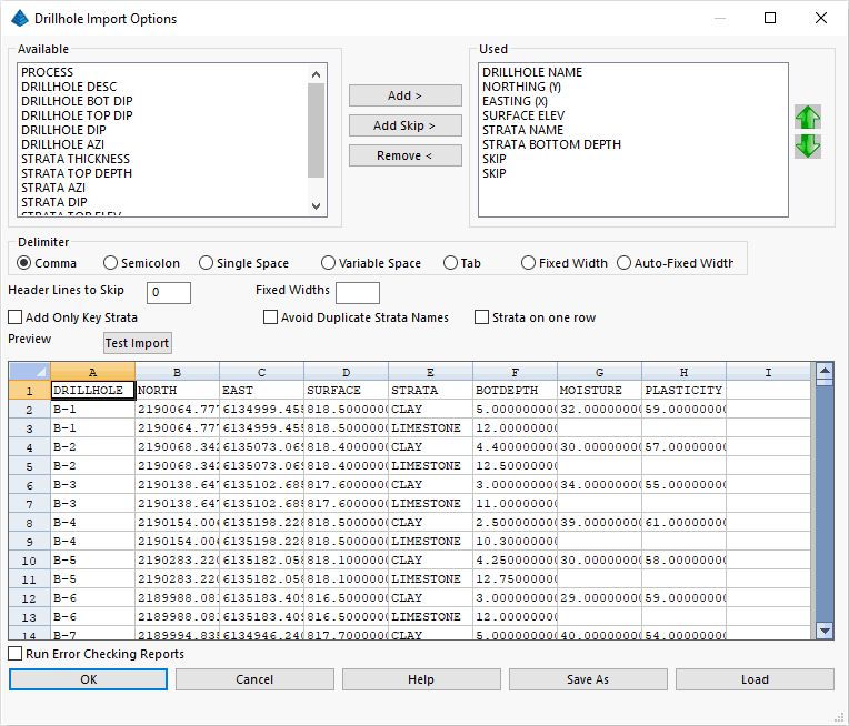
The drillhole data is imported into the project.
Select Drillholes to update.
[FILter]/<Select entities>: type ALL and press Enter twice
Re-select the drillhole file as illustrated earlier and click Open when ready:
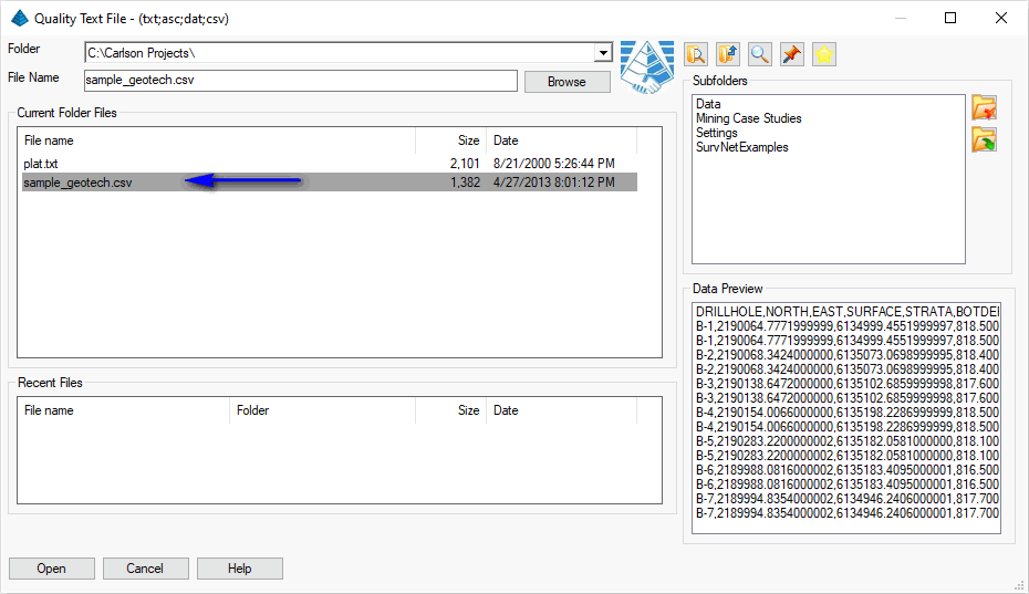
A Quality Import Options dialog box similar to that shown below appears:
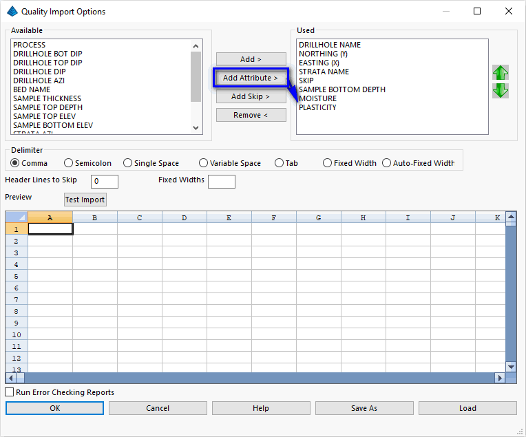
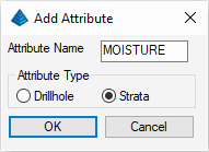
Use the Add >, Add Skip > and/or Remove < buttons to fill out the Used list at shown. Use the Add Attribute > button to create fields for the Moisture and Plasticity fields. When creating these fields, indicate they are Strata properties as illustrated below (click OK when ready):
Lastly, click the OK button on the Quality Import Options dialog box when ready to import the drillhole qualities.
Select Drillhole [<Select>/Name/Dialog]: press Enter
Select drillholes
[FILter]/<Select entities>: type ALL and press Enter twice
A dialog box similar to that shown below appears:
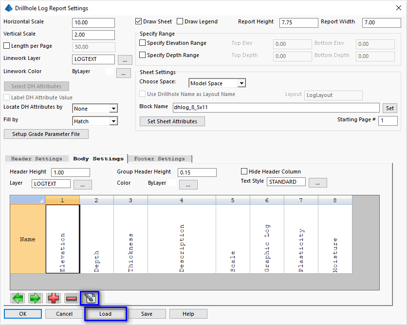
NOTE: The contents of the various Drillhole Log columns can be customized through the Edit Column button highlighted above.
Use the Load button to load a predefined Drillhole Log as shown below (click Open when ready):
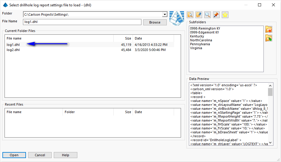
Click OK on the Drillhole Log Report Settings dialog box. When prompted:
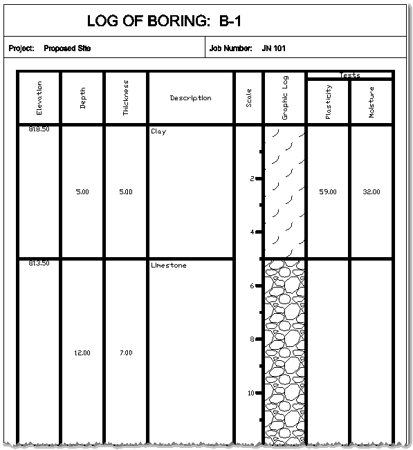
Pick a point to insert log report: pick an empty location within the drawing
An example of the report is shown below:
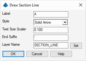
Fill out the dialog as shown above and click OK when ready. When prompted:
Pick 1st point: pick a location left of the building
Pick 2nd point: pick a location right of the building as illustrated below

Next, run the StrataCalc -- Geologic Column Profile command which displays a dialog box similar to that shown below:
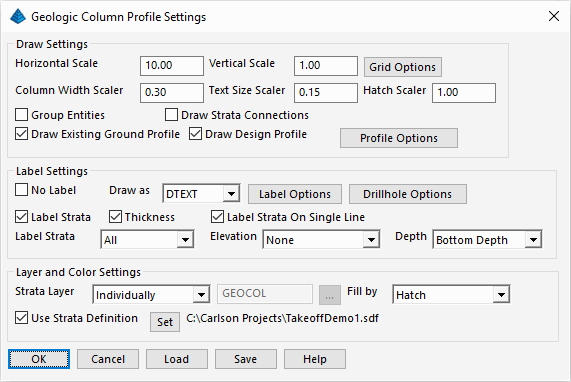
Set the values as shown above. Click the Set button to load the file saved in the Define Strata/Bed discussion section above. Use the table of sub-options outlined below within this command to further control the eventual report:
| Grid Options | Profile Options |
|---|---|
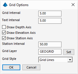
|
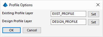
|
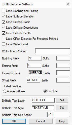
| Label Options | Drillhole Options |
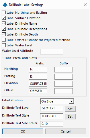
|
|
| Select Attributes (Prompt) | |
Select Drillholes for geologic column.
[FILter]/<Select entities>: type ALL and press Enter
[FILter]/<Select entities>: press Enter
Select Fence alignment polyline: pick the section "A" line created earlier
Maximum drillhole distance from alignment polyline <1000.0>: type 100 press Enter
Select Attributes (dialog): select the Attributes cited in the table above and click OK
Pick location for geologic column(s): pick a lower left location for the report
The report similar to that shown below is placed into the drawing:
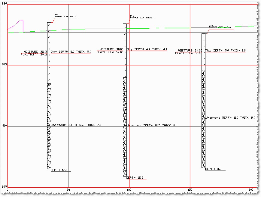
NOTE: As a reminder, complete the Takeoff/SiteNET Basics tutorial to see the Existing Ground and/or Design profiles.
 Set the values
as shown above and click OK when ready. When
prompted:
Set the values
as shown above and click OK when ready. When
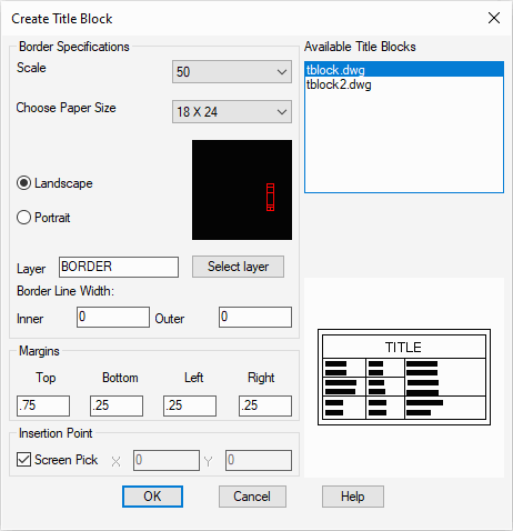
prompted:Pick location: pick a desired location for the Title Block
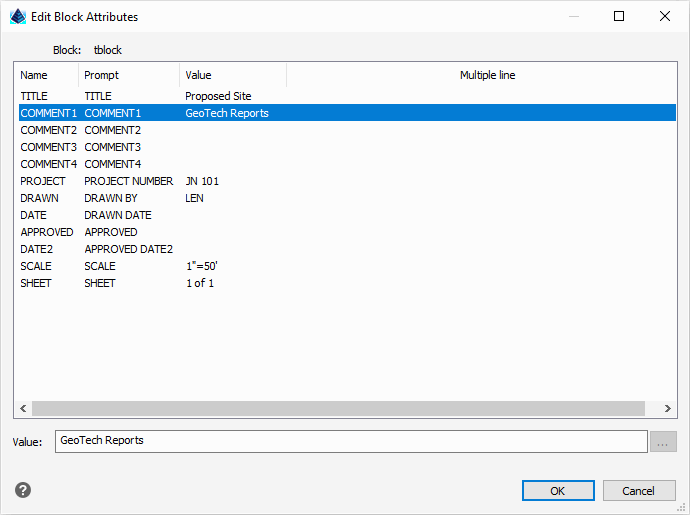
Enter attribute values: supply values as suggested below and click OK when ready
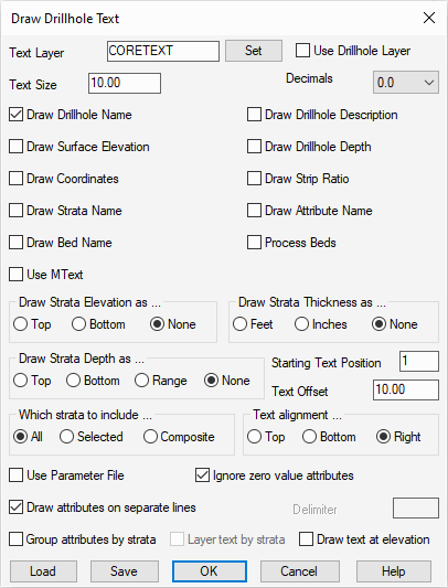
Set the values as shown above (a very minimal drillhole label) and click OK when ready. When prompted:
Select the Drillholes to label.
[FILter]/<Select entities>: type ALL and press Enter
[FILter]/<Select entities>: press Enter
Select Attributes (dialog): select the Attributes cited in the table above and click OK
Next, run the Map -- Bar Scale command to display the dialog box shown below:
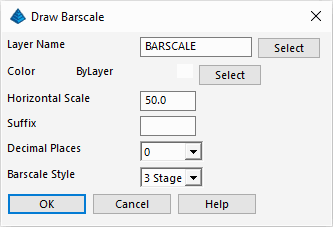 Click
OK when ready. When prompted:
Click
OK when ready. When prompted:Pick location for barscale: pick a desired location for the barscale
Next, run the Map -- North Arrow command to display the dialog box shown below:
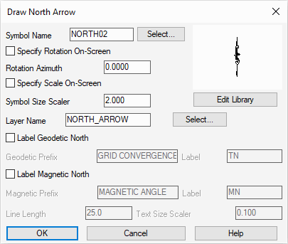 Click
OK when ready. When prompted:
Click
OK when ready. When prompted:Pick insertion point: pick a desired location for the North arrow
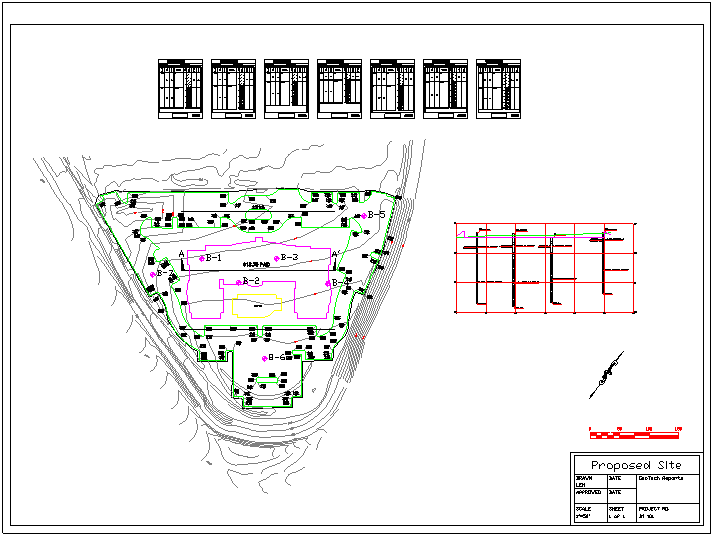
When complete, your drawing could resemble that shown below: