Config
Menu
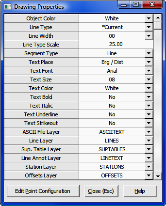
5.10 Drawing Properties (PR)
FUNCTION: The Drawing
Properties menu contains items that affect the appearance
of your drawing for objects and text placed in the drawing by COGO
routines.
Activate the Drawing
Properties routine by
picking
from the Config menu; by
pressing
[Alt][O], [D]; or by typing the two-letter command PR at any data entry
prompt.
 |
NOTE: Use the Point Configuration (PC -
Section
5.08) routine to set up text, layer, and symbol properties for
point entities. Click the [Edit Point
Configuration] button at the bottom of the Drawing
Properties window to activate the Point Configuration
dialog. |
The
Drawing
Properties window allows you to tailor "Sight" Survey’s drawing options to your own
preference. "Sight" Survey uses these settings to create your drawing in
the Drawing window. For example, when "Sight" Survey draws
a line, it creates the line using the values set for the Object Color,
LineType, Line
Width and Line Layer
properties.
Setting Values
To set a
Value (right-had column) for any
Property (left-hand
column),
follow these general instructions:
-
Select a Property by
clicking your mouse anywhere on the Property’s name or
in its Value box. A settings selection list will replace the Value box (except for Line Type Scale
which takes a manual entry).
-
Use your keyboard up and down arrows to scroll
through the available settings, or click the scroll bar next to the
selection list to pull down a settings
menu.
-
Select the desired setting with your
mouse, or use your keyboard up and
down
arrows to highlight the desired setting and then press [Enter].
-
When you are done making selections in
the Properties
window, click [Close] to close the Drawing Properties window.
|
NOTE:
If you prefer, you can leave
the Drawing
Properties
window open and drag it to another screen
location. Use the standard Windows technique for dragging windows to
a new location. |
 |
HINT:
Drawing properties set via the Drawing Properties window affect
subsequent items placed into the drawing. Properties do not
retroactively affect items already in the drawing. To change the
properties of an existing item in the drawing, use the procedures dictated
by your CAD application. |
Available Settings
Object Color: The Object
Color property is used to specify the color of the object (lines, arcs, etc.,
but not symbols or text) to be drawn.
When the Object Color is set to BY LAYER,
"Sight" Survey will draw all lines in the pen color associated with the layer
that is currently assigned to the line layer. To change the layer settings
refer to the Edit Layers (LA- Section 4.05) routine, or use commands in your CAD
application.
Line Type: The Line
Type property is used to specify the type of line that is drawn between
points. Several different line types may be available since this list
reflects the line types contained within the drawing or drawing
template.
When Line Type is set to BY
LAYER, "Sight" Survey will draw all lines
in the line type associated with the layer that is currently assigned to the
line layer. To change the layer settings refer to the Edit Layers
(LA- Section 4.05) routine, or use commands in your CAD
application.
Line Width: The Line Width property is used to
specify the width of line that is drawn between points. The available
values range from 1 to 10,
where the unit is in tenths of a millimeter.
When Line Width is set to BY LAYER,
"Sight" Survey will draw all lines in the line type associated with the layer
that is currently assigned to the line layer. To change the layer settings
refer to the Edit Layers (LA- Section 4.05) routine, or use commands in your CAD
application.
Line Type Scale: The
Line Type Scale property is used to control the visual scaling of line
types in the drawing. When set to 1, there is no scaling. Generally,
this value is determined by the drawing scale of the final printed
drawing. For example, if you plan to plot a drawing at 1" = 50', set your
Line Type Scale to 50 so that your
dashed and custom lines will plot correctly. To set or change a value,
simply type in the value. When changed, Line Type Scale will affect
all lines placed subsequent to the change in scale. To change the Line
Type Scale of an existing line: In AutoCAD and IntelliCAD, double-click on
the line then set the new Line Type Scale in the properties window that
appears; In MicroStation, select the line and in the Key-In box type
\LTSCALE x, where x is the scale factor.
Segment Type: The
Segment Type property is used to identify the nature of line segments to
be drawn. You may choose from: 3D Polyline; 2D Polyline; and
Line.
|
USING 3D POLYLINES IN AUTOCAD & INTELLICAD: In
some situations it may be desirable to draw lines between points of
differing elevation as 3D polylines. Be aware that in AutoCAD and
IntelliCAD, 3D polylines cannot contain arcs, display linetypes, or show
width or thickness. However, you can assign a linetype style to a 3D
polyline and it will retain the information. Simply save the
drawing, explode the 3D polylines before you plot, then undo to restore
the 3D polylines.
|
Text Place: The Text
Placement property is used to
specify how you want "Sight" Survey to annotate lines or place text on the
drawing. The available options are:
-
/ Brg
- annotates
lines with the bearing below the line.
-
/ Brg Dist
- annotates
lines with both bearing and distance below the line.
-
/ Dist
- annotates
lines with the distance below the line.
-
/ Label
- annotates
lines with a label below the line. After you enter the label, “Sight”
Survey will use that label for all lines drawn until a different text
placement option is selected.
-
Brg /
- annotates
lines with the bearing above the line.
-
Brg / Dist
- annotates
lines with the bearing above the line and distance below the line.
-
Brg Dist /
- annotates lines with both bearing and
distance above the line.
-
Dist /
- annotates
lines with the distance above the line.
-
Dist / Brg
- annotates lines with the distance
above the line and the bearing below the line.
-
Label /
- annotates
lines with a label above the line. After you enter the label, “Sight”
Survey will use that label for all lines drawn until a different text
placement option is selected.
-
None - Shuts off the line and arc
annotation.
Text Font: The Text
Font property is used to
specify the name of the text font you want to use for the text on your
drawing. "Sight" Survey does not contain any fonts. The drop-down
list will contain all of the fonts installed on your computer.
Text Size: The Text
Size property is used to
specify the size of the text to be placed on your drawing. Sizes range
from 1 to 100, where each increment equals 1/100 of an
inch. For those
familiar with Leroy lettering templates, these sizes (x 10) will equal Leroy
sizes; e.g. 8 = Leroy 80.
The actual plotted text size is determined entirely by the
final scale that the drawing is plotted at. If you plot the final drawing
at a scale that is different from what you entered for a final scale when you
started the drawing in "Sight" Survey, your text size will not be correct.
For example, if you enter the final scale as 100 within "Sight" Survey, but you
actually plot the drawing within CAD at a 50 scale, your text (and symbols) will
be double their expected size.
When a line being annotated is too short to support the text
being placed on it, a label will be assigned to the line and placed above the
line. The label will begin with the letter "L" and follow
with a number that represents that line in the Short Line
Table (SL - Section 12.04) which can later be placed on your
drawing.
"Sight" Survey’s course of action depends upon
the Short Line
Distance setting in the CAD
Configuration menu (CM - Section
5.03).
Text Color: The Text
Color property is used to specify the color of the annotation and notation text
to be drawn. Text Color operations are basically
identical to setting the Object Color.
When the Text Color property is set to
BY
LAYER, "Sight" Survey will place all text in the
color associated with the layer that is currently assigned to the layer for the
type of text being placed. For example, Bearings are placed in the
color assigned to the Line
Annotation Layer, etc.)
Text Bold: The Text
Bold property is used to specify whether or not you want the drawing text to
be placed in a bold typeface. When Text Bold is
Yes, text will be placed in a darker, bold typeface. When
Text Bold is No, the text
will be placed in a regular typeface.
Text Italic:
The Text Italic property is used to specify
whether or not you want the drawing text to be placed in an italic
typeface. When Text Italic is
Yes, text will be placed in an italic typeface. When
Text Italic is No, the text
will be placed in a regular typeface.
Text Underline: The Text Underline property is used to specify whether or not you want the
drawing text to be underlined. When Text Underline is Yes, text
will be placed in an underlined typeface. When Text Underline is No, the text will be placed in a regular typeface.
Text Strikeout: The Text Strikeout property is used to specify whether or not you want the drawing text to
be placed with a strikeout, such as this. When
Text Strikeout is Yes, text will be
placed with a strikeout. When Text Strikeout is No, the text will be placed in a regular typeface.
ASCII File Layer: The ASCII
File Layer property is used to specify the name of the layer for imported ASCII text
files. The default name for this layer is ASCIITEXT. Click [q] to select a layer, or simply type in
the name of a new or existing layer.
|
HINT:
For any of the Layer properties, if the layer you wish to use has not yet been
defined, add it by typing the new layer name into the Value
(right-hand) column. New layers that are added in this manner
(versus using Edit
Layers) are only created and
saved in the drawing file if they contain data or are set as the current
value for a Property (left-hand column) when the file is
closed. |
Line Layer: The Line
Layer property is used to specify the name of the layer for lines, arcs, random
curves, circles, rectangles, and custom lines (including text and symbols placed
along custom lines). The default name for this layer is
LINES. Click [q] to select a layer, or simply type in
the name of a new or existing layer.
Sup. Table Layer: The Supplemental Table Layer property is used to specify the
name of the layer for the curve and short-line tables. The default name
for this layer is SUPTABLES. Click [q] to select a layer, or simply type in
the name of a new or existing layer.
Line Annotation Layer: The Line Annotation
Layer property is used to specify the name of the layer for bearings,
distances, curve lengths, curve labels, and short-line labels.
The default name for this layer is
LINETEXT.
(Text characters drawn as a part of a custom line are placed
on the Lines
Layer.) Click [q] to select a layer, or simply type in
the name of a new or existing layer.
Station Layer: The Station Layer property is used to specify the
name of the layer for stationing. The default name for this layer is STATIONS. Click [q] to select a layer, or simply type in
the name of a new or existing layer.
Offsets Layer: The Offsets Layer property is used to specify the
name of the layer for offset lines and annotation when they are placed by
various perpendicular offset routines. The default name for this layer is
OFFSETS. Click
[q] to select a layer, or simply type in the name of a new or existing
layer.
[Edit Point
Configuration]: Click this button to call the Point
Configuration routine (PC - Section
5.08).