Config Menu
5.08 Point Configuration (PC)
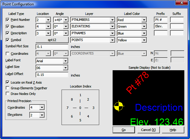
FUNCTION: The Point Configuration routine is a visual interface that allows you to setup how "Sight" Survey draws points on the drawing.
Activate the Point Configuration routine by picking from the Config menu; by pressing [Alt][O], [P], or by typing the two-letter command PC at any data entry prompt.
Label Type: Select the elements you want drawn at each point, then for each element select the parameters as described below. You may draw up to five elements at any point, including: point number; elevation; description; symbol; and coordinate values.
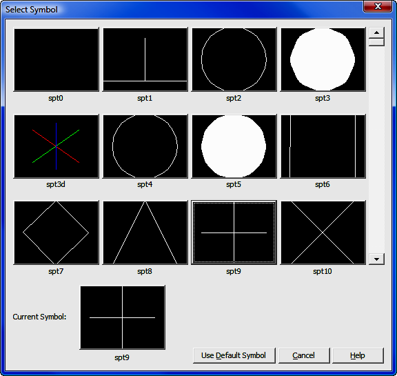
Symbol: Click the button to select a symbol to be drawn at the point. This symbol will be used unless a symbol has been previously assigned to a point by one these methods:
If you have used the Point Manager (PM - Section 6.09) to assign or change the symbol associated with the point, the setting in the Point Manager will override any symbol set in this Point Configuration routine.
If you have coded this information in the field, the Draw Field to Finish (FF - Section 6.33) routine will use your field-coded symbols during field-to-finish processing. Once Draw Field to Finish has been run, these symbols are assigned to their respective points. You may change the association by using the Point Manager, but running Draw Field to Finish again will reset it to the field-coded symbol.
To select a symbol, use the slider bar on the right side of the Select Symbol dialog until the desired symbol is visible, then left-click on the symbol.
Symbol Plot Size: Enter the size for plotted symbols. This size is relative to the selected drawing scale set in CAD Configuration (CM - Section 5.03). For example, if you have set your drawing scale to 1" = 100' and your symbol plot size to be 0.10", that is the size symbols will appear on your plotted drawing. If you should change your drawing scale to 1"=50', those same symbols would double in size and be plotted to 0.20".
Location: Click [q] to select a location at which that particular element will be drawn. Refer to the Location Index to the left of the Sample Display.
Angle: Click [q] to select an angle at which that particular element will be drawn. You may choose from -90° to 90° (0° is horizontal), or at any 10° increment in between. There are also available settings at 45° and -45°.
Layer: Click [q] to select a layer upon which to draw the element. For Symbols, this layer will be used unless a point layer has been previously assigned to a point by one these methods:
If you have used the Point Manager (PM - Section 6.09) to assign or change the layer associated with the point, the setting in the Point Manager will override any symbol layer set in this Point Configuration routine.
If you have coded this information in the field, the Draw Field to Finish (FF - Section 6.33) routine will use your field-coded symbols and layers during field-to-finish processing. Once Draw Field to Finish has been run, these symbols and layers are assigned to their respective points. You may change the association by using the Point Manager, but running Draw Field to Finish again will reset it to the field-coded symbol and layer.
Label Color: Click [q] to select a color in which that particular element will be drawn.
Prefix: Enter an optional prefix to be placed as part of the element. For example, you might want to add Pt # as a prefix to your point numbers, or Elev. as a prefix to your elevation values. Be sure to include any spaces you may want to place between the prefix and the element.
Suffix: Enter an optional suffix to be placed as part of the element. For example, you might want to add Elev. as a suffix to your elevation values. Be sure to include any spaces you may want to place between the element and the suffix.
Label Font: Click [q] to select a text font in which the labels will be drawn. While you can mix label colors, you cannot mix label fonts or sizes.
Label Size: Click [q] to select a text size in which the labels will be drawn. While you can mix label colors, you cannot mix label fonts or sizes.
Label Offset: Enter the distance of separation from the point to the point label. This is the actual distance between the two elements when the drawing is plotted at the specified scale. The units are controlled by your selection of Distance Units in the Local Configuration menu (LC - Section 5.05).
Locate on Real Z axis: Check this setting if you want the symbol and related elements to be placed into the drawing at the real elevation (z-axis) of the point. If unchecked, the elements will be drawn at a zero elevation.
Group Elements Together: Check this setting if you want all the elements for each point to be grouped together. Grouping the elements will make it easier to move or remove a point and all associated elements from the drawing.
Draw Nodes Only: Select this setting to draw only the point entities (nodes) with no annotation. Points can act as nodes to which you can snap objects. You can specify a full three-dimensional location for a point. Node appearance is controlled in AutoCAD and IntelliCAD by the system variables PDMODE and PDSIZE. In MicroStation, the point node is actually a zero-length line. See Section 6.11 for additional information.
Printed Precisions: Printed precision is nothing more than the number of places that your CAD annotation will be carried out to. The settings here are for CAD annotation only. Settings for printed precision have nothing to do with the internal precision of calculations. Your choices are: Coordinates - 0 to 6; Elevations - 0 to 3.