Points Menu
6.33 Draw Field to Finish (FF)
FUNCTION: The Draw Field to Finish routine is used to turn data collector field notes into a final CAD drawing by matching the descriptions of the field points with user-defined codes. The points are brought into the drawing with attributes defined by the code, including the layer, symbol, size and linetype.
Activate the Draw Field to Finish routine by picking from the Points menu, by pressing [Alt][P], [H], or by typing FF in any text box.
This section covers these main dialog screens, along with their peripheral dialog screens.
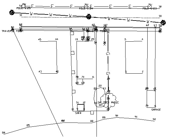
Example drawing results using the example points and example code definitions
Two files are used in Draw Field to Finish - a coordinate file and a field code definition file. The coordinate file consists of x,y,z points with text description fields. The description fields contain codes for the Draw Field to Finish processing. The coordinate file can be a Carlson coordinate (.CRD) file, C&G CRD file, C&G CGC file, Land Desktop MDB file or Simplicity Systems ZAK file. An ASCII data file can be converted into a coordinate file using the File > Import > ASCII Files (see Section 3.08) routine. The field code definition file defines the layer, symbol, size and other actions to apply with each code.
Draw Field to Finish can translate the field points into Carlson points (also called coordinate geometry points or cogo points) with a symbol, layer, and size defined by the code. The point settings of whether to label the description, point number, and elevation and whether to locate the point at zero or at the real Z can be found in the Additional Draw Options of the Draw Field to Finish dialog box. The Draw All Points (DL - Section 6.11) command has these point settings stored separately using the Point Configuration (PC - Section 5.08) menu. Draw All Points provides a simpler method for drawing points compared with Draw Field to Finish .
There are two different methods for connecting linework. One method creates line work by connecting points with the same code. The linetype is defined by the code as either points only (no line work), lines, 2D polylines, both 2D and 3D polylines, or 3D polylines (breaklines). Distinct lines with the same code are defined by adding a group number to the end of the code name in the data file. With this method, all points with the description CODE1 will be one line while points with CODE2 will be another line. Both CODE1 and CODE2 use the definition for CODE. For example, the code EP could be a code for edge of pavement that is to be connected as 3D polylines. If there are two separate edge of pavement lines on the left and right sides of a road, all the points for the left side could have the description EP1 and the points on the right side could be EP2.
The second method is the PointCAD format. This method also connects points with the same code. The difference is that instead of using a number after the code for distinct lines, you use the same code with an additional code for starting and ending the line. For example, +0 is used to start a line and -0 to end. So the coding for a segment of edge of pavement could be EP+0, EP, EP, EP-0. Another special code that has been added to Field to Finish is +7, -7. This 7 code will use the linetype definition of line, 2D polyline or 3D polyline defined by the Draw Field to Finish code. For example, if EP is defined as a 3D polyline, then the coding EP+7, EP, EP, EP-7 will create a 3D polyline. Otherwise codes like +0, -0, which is defined as start and end line, will draw EP as a line. Other PointCAD special codes are: +4 starts a curved 2D polyline, *4 starts a closed curved 2D polyline, +1 begins a 3-point arc, +5 starts a 3D polyline, *5 starts a closed 3D polyline, +6 starts a 2D polyline, *6 starts a closed 2D polyline, +7 starts a line whose type is specified by the field code definition, -05 starts a curved 3D polyline section, -50 ends that section, +8 starts a 2D and 3D polyline combination, *8 starts a closed 2D and 3D polyline combination, -08 starts a 2D and 3D polyline combination curved section, -80 ends that section. //, followed by a field code, concatenates that field code's description on to the point's description. For example, OAK//04 might become LIVE OAK TREE 4" if the field code OAK translates to LIVE OAK TREE and the field code 04 translates to 4".
The advantage to the PointCAD method is that you don't have to keep track of line numbers. For example, if you are surveying 50 curb lines, the first method would require you to use 50 distinct curb numbers. The advantage to the first method is that you don't have to use the start and end codes. Also the Nearest Found connection option applies to the first method.
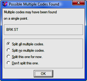
When "Sight" Survey first begins the Draw Field-to-Finish routine, your data file is scanned for multiple codes. If any are found, this is the first dialog you will see.
Multiple codes are defined by including each code in the point description field separated by a space. A single data point can be used in different lines by assigning it multiple codes. For instance, a point might be part of both a curb line and a driveway line with a description of "CURB DRW". Field-to-Finish uses spaces as the delimiter for multiple codes. You should avoid spaces in the descriptions except for where multiple codes are intended or after the "/" character. For example, a code for light post should not be "LGT POST" but instead should be "LGTPOST".
There are options for the handling of multiple codes when encountered. The Split All option will split all multiple codes and process each code based upon their code definition. When Split No is selected both codes will be processed based upon their code definition. When Field-to-Finish detects multiple codes on a point the following dialog will be displayed with options for handling the codes.
The main dialog box for Draw Field to Finish is shown below:
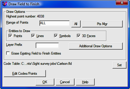
Range of Points: Specify the range of points to draw. Click [All] to process all points in the file, or click [Pts Mgr] to use the Point Manager (PM - Section 6.09) to select the points to use.
Entities To Draw: The Points option draws only the points and point attributes; the Lines option draws only the linework; the Symbols draws only the symbols; and 3D Faces draws only the 3D faces. Any combination of these options can be processed as well as individual processing of each entity.
Layer Prefix: Optional layer prefix added to all entities drawn with Draw Field to Finish.
Erase Existing Field to Finish Entities: When checked, this option will erase from the drawing any old entities created by previous field-to-finish runs before drawing the new entities.
[Additional Draw Options]: Click [Additional Draw Options] to select additional options. (See below)
[Set]: Click [Set] to select the code table to use for field-to-finish processing.
[Edit Codes/Points]: Click [Edit Codes/Points] to edit the field codes. (See below)
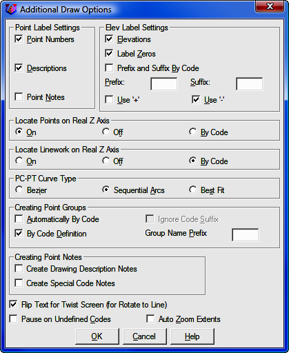
Point Label Settings: Specify whether you want Draw Field to Finish to label the Point Numbers, Descriptions, and/or Points Notes which are contained in the note (.NOT) file that is associated with the coordinate (.CRD) file.
Elev Label Settings: Specify the elevation labeling options. The Label Zeros option will label the elevations of points with z=0. Use Parentheses will place parenthesis around the elevation text. Use '+' and Use '-' will place the appropriate symbol in front of the elevation.
Locate Points on Real Z Axis: Choose between locating all the points at real Z elevation (On), all at zero elevation (Off), or to use the real Z setting as defined in the individual codes (By Code).
PC-PT Curve Type: Sets the method for drawing curves with more than 3 points. The Bezier option draws a smooth polyline through all the curve points. The Sequential Arcs method draws multiple arcs with arc end points at each of the curve points. These arcs are tangent to the preceding line segment. The Best Fit method creates a single best-fit curve for all the curve points between the PC and PT.
Creating Point Groups: This option is not currently supported by "Sight" Survey.
Creating Point Notes: This option is not currently supported by "Sight" Survey.
Flip Text for Twist Screen: This option is not currently supported by "Sight" Survey.
Pause on Undefined Codes: When checked, Draw Field to Finish will pause if it encounters a description that is not defined in the code table.
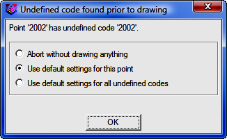
Abort without drawing anything: This stops the Draw Field to Finish routine. Run Draw Field to Finish again to correct the code table.
Use the default settings for this point: This option draws a point in the "MISC" layer with no linework. To set your own default, define a code called "SC_DFLT".
Use default settings for all undefined codes: This option will draw all undefined codes in the "MISC" layer by default or a user specified layer as defined in the "SC_DFLT" code. A good way to check the data file for unmatched descriptions is to use the Print Table command and choose the Data Points and Distinct Code options. This command will print the different codes in the data file and identify any undefined codes.
Auto Zoom Extents: When checked, this will force a zoom extents after Draw Field to Finish is done.
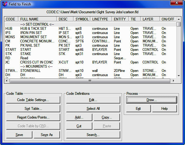
The Field to Finish dialog box (shown below) allows you to load the coordinate and field code definition files, view and edit the code definitions, view and edit the coordinate file, view reports, and then return to the Draw Field to Finish dialog box to process the files. The top section displays the code definitions. The bottom section has three columns of functions each pertaining to controls for different elements of the command. The Code Table section provides controls for settings, sorting and reporting of codes. The Code Definitions section provides tools for the creation and editing of codes. The Coordinate File section provides controls for coordinate files and points. It also contains the Draw controls which starts the processing of the data using Draw Field to Finish.
Click the [Code Table Settings] button for options that provide tools for defining the coding method to be used for processing of the point data. Various import tools allow for the importing of codes from different software packages. Controls for handling multiple codes are located on this dialog. All special codes can be replaced to other characters defined by the user. The special codes are listed and edited on this dialog.
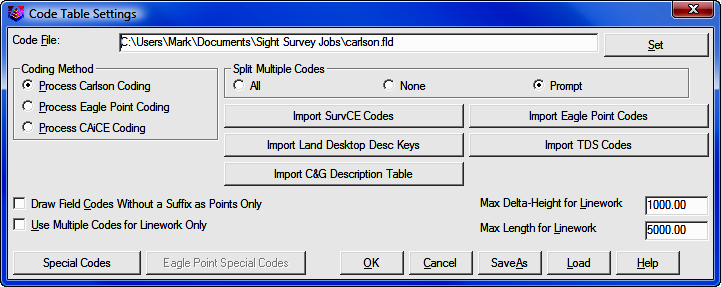
[Set]: Choose this button to specify a new code table. The name of the current table is shown in the field to the left of this button.
Coding Method
Three Coding Methods are offered: Carlson; Eagle Point; and CAiCE.
¤ Process Carlson Coding: When selected, this option interprets and processes coordinate files based upon the Carlson Coding method and data collection method.
¤ Process Eagle Point Coding: When selected, coordinate files are processed based on the Eagle Point Data Collection method and the Eagle Point Codes button becomes available for selection displaying the following dialog. This dialog allows for customization of the eagle point special designators.
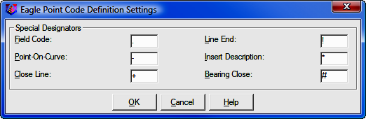
Currently the supported designators include, Field Code, Point-On-Curve, Close Line, Line End, Insert Description and Bearing Close. Also supported is the ability to recognize overwriting of descriptions just as Eagle Point does by using the space separator instead of the Insert Description designator. Examples of supported coding are as follows:
.TC Places a node and or line per the field code library.
TC Places a node and or line per the field code library.
-TC Specifies a point on a curve.
TC- Specifies a point on a curve.
..TC Stops the line.
TC! Stops the line.
.TC+ Closes the line back to the starting point.
TC+ Closes the line back to the starting point.
.TC# Typically coded on the third corner of a rectangle to close the figure with having to locate the fourth corner.
TC# Typically coded on the third corner of a rectangle to close the figure with having to locate the fourth corner.
WV.W1 Places a node as specified by the code "WV" in the field code library and then begins a line as specified by code "W" in the field code library.
.TC.EP.FL Results in three lines coming together.
TC1.TC2.TC3 Results in three lines coming together. All three lines are specified by the definition of the single code "TC" in the field code library.
TC.TC1 When used in conjunction with the "Draw Field Codes Without a Suffix as Points Only" toggle, "TC" will be recognized as the node and "TC1" will be recognized as the line so that if the code "TC" in the field code library is defined as a polyline, line or 3D polyline, duplicate lines will not be unintentionally placed when this shot only pertains to a single element. Keep in mind that all line work must have a numeric suffix when using this toggle.
TREE * OAK Result on screen would be: TREE OAK
TREE OAK * Result on screen would be: OAK TREE
TREE OAK Result on screen would be: OAK
TC1!.TC2-.VLT6# Stops "TC1", continues "TC2" as a point on a curve and closes VLT6 as a rectangle using the "Bearing Close" code.
The use of the Use Multiple Codes for Linework Only toggle is recommended when using Eagle Point Coding.
¤ Process CAiCE Coding: When selected, coordinate files are processed based on the CAiCE Data Collection method. Examples of supported coding are as follows:
169 is just the code 169.
145C10 is the code 145 and line #10.
169C25C is the code 169, line #25, and the point is on a curve.
172C12B is the code 172, line #12, and this point closes the line.
Split Multiple Codes: The All option will split all multiple codes and process each code based upon their code definition. When None is selected both codes will be processed based upon their code definition. When Prompt is selected and Field-to-Finish detects multiple codes on a point a dialog will be displayed with options for handling the codes. (See above)
Import Eagle Point Codes: This option imports Eagle Point codes into the Carlson Field to Finish (fld) code definition file.
Import Land Desktop Desc Key: This option imports and converts a Land Desktop Description Key into a Field to Finish (fld) code definition file. The Land Desktop Description Key file is an mdb file and is found in the Land Desktop Project file path. It is located in the under the COGO/DescKey directory.
Import TDS Codes: This option imports TDS codes into the Field to Finish (fld) code definition file.
Import C&G Description Table: This option imports C&G code tables (tbl) into the Field to Finish (fld) code definition file.
Import SurvCE Codes: This option imports a SurvCE Feature Code List (fcl) into a Field to Finish (fld) code definition file.
Draw Field Codes Without a Suffix as Points Only: This option is useful for when wanting to use a field code sometimes for linework and sometimes for just points but it is preferred to number the lines rather than using start and stop codes. For example, if the field code EP is defined to use the Line Entity type, then EP25 will be drawn as a Line, however if just EP is used, no linework will connect to that COGO point.
Use Multiple Codes for Linework Only: When checked, and when multiple codes are detected, only linework will be drawn for the secondary codes. Points are only created based on the primary code. If you want symbols for all multiple codes, then this setting should not be checked.
Max Delta-Height for Linework: Use this option to specify the maximum elevation difference that Draw Field to Finish should draw any section of linework. This option is for use with 3d polylines and lines.
Max Length for Linework: Specify the maximum length that Draw Field to Finish should draw any section of linework.
This section allows you to substitute the existing predefined special codes and characters with your own. Draw Field to Finish recognizes several special codes. A special code is placed before or after the regular code with a space separating the code and special code. Here is a listing of the default special codes and characters.
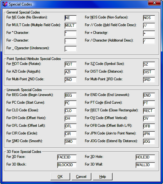
Special Characters
The characters (*, -, +, /, and _) can be used and substituted in Draw Field to Finish. The way these characters are used is that when the file is processed the description field is searched for these characters. If the "+" symbol was changed to "-" then the program would look for "-" and change it to "+". This is useful when a particular data collector may not have all the symbols available. With these substitutions you can make a character that is provided on the data collector generate the symbol needed. Multiple characters can also be used. For example "--" can be used to in order to produce a "/" character or any of the characters listed above.
Special Codes
"/"
Carlson points in the drawing have point attributes including a description. When Field-to-Finish draws the points, the point description from the coordinate file is processed to match a code. The code then defines the description that is drawn with the point. For example, consider a code of "UP" with a description of "POLE" and a data point with the description "UP". The data point description "UP" would be matched with the code "UP" and the point would end up being drawn with the description "POLE". A special character "/" (the forward slash or divide key) can be used for an unprocessed description to append. Everything after the "/" is added directly to the point description and is not considered a code and no further substitution is done on it. For example, a data point with the description "UP / 150" with the same code "UP" definition above would be drawn with the description "POLE 150".
"//"
This special code causes text after the "//" to be interpreted as a field code. That field code's description is then appended to the first field code's description. For example, if the field code 02 has the description 2" and the field code OAK has the description oak tree, then 02//OAK will result in the point having the description of 2" oak tree. If the "/" character has been replaced with a different character, for example with a & character, then the "//" code would become "&&".
PC
This code begins a three point arc or a curved line when used with the "PT" code (see below). The point with this special code is the first point on the arc. The next point with the code is considered a point on the arc, and third point with the code is the arc endpoint. For example (in point number, X, Y, Z, description format),
10, 500, 500, 0, EP PC - start curve
11, 525, 527, 0, EP - second point on curve
12, 531, 533, 0, EP - end point of curve
PT
This is a special code that can be used with "PC" to define a curve with more than three points or a tangent two-point curve. Starting at the point with the "PC", the program will look for a "PT". If the "PT" is found, all the points between the "PC" and "PT" are used for the curve which is drawn as a smoothed polyline that passes through all points and only curves the polyline between points. If no "PT" is found, then the regular three point arc is applied as explained above. If no points are found between the "PC" and "PT", then the point prior to the "PC" and the point after the "PT" are used to create tangents for the resulting curve.
CLO
This code forces the lines drawn between a series of points with the same code to close back to the first point with the same code. For example, shots 1-4 all have the BLD description with the exception of point 4. Its description is BLD CLO. This will force the linework drawn for the BLD code to close back to point 1 which is the first point with the description of BLD.
NE
This code represents no elevation. A point with this special code is located at zero elevation.
NOS
This code indicates that the point should be "non-surface"; that is, that it should be ignored when contouring or creating surfaces. This can also be controlled per-field code by turning on the Non-Surface toggle in the Edit Field Code Definition dialog box.
OH & OV
The codes "OH" and "OV" stand for offset horizontal and offset vertical. These offset codes apply to 2D and 3D polylines. A single set of offset codes can be used to offset the polyline a set amount. For example,
10, 500, 500, 100, EP OH2.5 OV-.5
11, 525, 527, 101, EP
12, 531, 533, 103, EP
This would create a polyline connecting points 10,11 and 12 and an offset polyline with a 2.5 horizontal and -0.5 vertical offset. The direction of the horizontal offset is determined by the direction of the polyline. A positive horizontal offset goes right from the polyline direction and a negative goes left. The horizontal and vertical offset amounts apply starting at the point with the offset codes until a new offset code or the end of the polyline. Only one horizontal and vertical offset can be applied to 2D polylines. For 3D polylines, multiple offset codes can be used to make a variable offset. For example,
10, 500, 500, 100, EP OH2.5 OV-.5
11, 525, 527, 101, EP OH5.5 OV-.75
12, 531, 533, 103, EP OH7.5
This would offset the first point horizontal 2.5 and vertical -0.5, the second point horizontal 5.5 and vertical -0.75 and the third point horizontal 7.5 and vertical -0.75.
SZ
This code is used to set a different symbol size. The value of the new symbol size is specified after the SZ (example SZ0.2). This value is a size scaler that is multiplied by the current drawing scale to determine the actual drawn size. For example, a drawing scale of 50 and a symbol size scaler of 0.2 would make the drawn symbol size 10. Two dimensional scales can be accomplished by using an `X' between the horizontal and vertical scales (e.g., "SZ0.2X3.5"). If no number follows the SZ special code, then the next point with the same field code as the current point will be used to determine the scale factor.
ROT
This code is used to set the rotation of the point symbol. If a point number follows the ROT code, then angle from the current point to this point number is used for the rotation. For example, "ROT45" would rotate the symbol towards point number 45. If there is no point number after the ROT code, then the rotation point is the next point number with the same code as the current point. ROT can also be used to rotate towards an angle clockwise from north by using `+' or `-' in front of the number. For example ROT+45 rotates the point symbol to the northeast and ROT-90 rotates the point symbol to the west.
SMO
This code is used to smooth the polyline.
AZI & DIST
The AZI and DIST codes are used together to locate an offset point. The AZI sets the offset azimuth and DIST sets the distance. The values should directly follow the code. For example, AZI25 DIST4.2 would draw the point offset 4.2 at an azimuth of 25 degrees.
JOG
The "JOG" special code allows for additional points to be inserted into the line work at perpendicular or straight offsets. Only offsets should follow the JOG code. Positive numbers indicate a jog to the right and negative numbers indicate a jog to the left. Alternatively, "R#" and "L#" can be used where # is the distance to either the right or the left. Finally, "S#" can be used to make an offset straight ahead by using a positive # or behind by using a negative #. For example, "BLDG JOG S10.1 R5 L12.2 L5 L12.2" or equivalently "BLDG JOG S10.1 5 -12.2 -5 -12.2" advances 10.1 units and then draws a closed rectangle on the right hand side of an existing line. The offsets are always done in the X-Y plane. If the current line is vertical, an offset to the right is along the positive X-axis.
JPN
The "JPN" (Join to Point Name) special code joins to the point named immediately after the code. For example, "JPN205" causes a line to be drawn from the current point to the point "205".
RECT
The "RECT" special code causes a rectangle to be formed on a 2D or 3D polyline using one of two different methods. If a number follows "RECT" (e.g., "RECT10"), a rectangle will be drawn 10 units to the right of the last two points ending on the point with the "RECT" code. Use a negative offset to place the rectangle on the left side (e.g., "RECT-2.5"). For example if locating the left side of a 10' rectangular concrete pad using the code conc for concrete, the description of the two left points would be (conc) for the first point and (conc rect10) for the second. If no number follows "RECT", then the polyline will be closed by shooting right angles from the first point of the polyline and the current point and creating a new point where those two lines cross. This method requires three points be established on the pad.
CIR
The "CIR" special code stops the linework on the previous point and causes this point to create a circle in one of three different ways. The first way uses just the current point as the center with the CIR special code followed immediately by the radius. For example "CIR5.0" will create a circle centered on this point with radius 5 and at the elevation of the current point. The second method uses two points, the first point specifying the center and the elevation, and the second point specifying the radius. The third method uses 3 points that specify the perimeter of the circle in 2D with the first point specifying the elevation. The "CIR" code can be used with all of the linetypes including "points only". The circles are always parallel to the X-Y plane.
For Multi-Point 2ND Code
When used on the first point of a multi-point symbol, the "2ND" code indicates that the second point of the sequence (i.e., the next point after the current one) should be used as the second symbol insertion point for a multi-point symbol. Please refer to Symbol Pts in the Edit Field Code Definition section below.
For Multi-Point 3RD Code
When used on the first point of a multi-point symbol, the "3RD" code indicates that the third point of the sequence should be used as the third symbol insertion point. The "3RD" code should be used with the "2ND" code. Please refer to Symbol Pts in the Edit Field Code Definition section below.
(Edit Codes / Points) dialog continued...
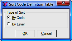
Sort Table
Click the [Sort Table] button to sort the code table by either code name or layer.
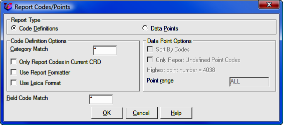
Report Codes/Points
Click the [Report Codes/Points] button to print the code table or the data file to the screen, file, or printer. A useful option here is to print the data file (CRD Points) and choose Sort by Codes which will group the data points by distinct codes.
Code Table by CRD
Click the [Code Table by CRD] button to create code table definitions based on the coordinate file field descriptions. This is useful when creating a code table from scratch.
Save
Click the [Save] button to save the Field to Finish field code definition (.FLD) file.
Save As
Click the [Save As] button to save the Field to Finish field code definition (.FLD) file. but allow for the specification of a different file name and location to save to.
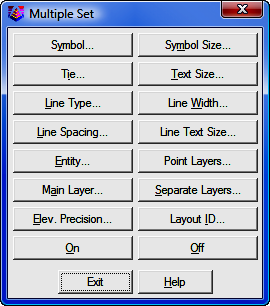
[Edit]: If only one field code is selected, then this command opens the Edit Field Code Definition dialog box. If multiple field codes are selected (by holding down the control key or shift key and clicking on the rows), then the Multiple Set dialog box will open.
Field-to-Finish will layerize the points and linework according to the code definitions. If the layers to use are not already defined, Field-to-Finish will create the necessary layers and assign different colors. To have the same colors for these layers in all your drawings, define the layers in the prototype drawing. The prototype drawing is the default drawing that is loaded whenever a new drawing is created. To define layers in the prototype drawing, save your current drawing and then start a new drawing with the New command. Don't give the new drawing a name, just click OK. Then define the layers as desired with the Layer command. When you are done creating layers, use the Save As command and change to Drawing Template (.DWT) under Save as Type. The default drawing template that is used is named 18SCDRAW.DWT. This template name will correspond to the version of AutoCAD that is being used, for example 16SCDRAW for AutoCAD 2004 users. You can overwrite this default template or make a new drawing template.
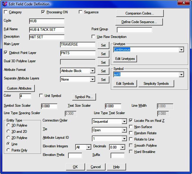
Category: This is an optional field that can to used to help organize your codes. A category is not used for processing and only is useful in viewing and printing.
Processing ON: This toggle controls whether this code will be processed.
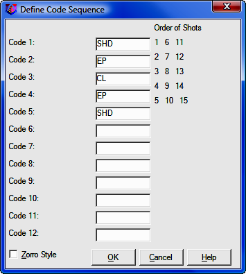
Sequence: This specifies a sequence type code. Sequences are a way to simplify field entry of a sequence of codes. For example, a road cross-section could be SHD1 EP1 CL EP2 SHD2. Instead of entering these different descriptions, one sequence definition can store these descriptions in order. Then just the sequence code (such as RD) is used in the field. The cross-section can be shot in left-to-right then left-right order, right-to-left then right-to-left order, or alternating left to right then right to left order. The alternating method is known as the Zorro style. The one restriction is that the shots always start from a right or left edge.
To set up a sequence, choose the Sequence toggle in the Edit Code dialog. Then click the [Define Code Sequence] button to bring up a dialog for entering the sequence codes in order. These sequence codes should be defined as normal codes somewhere else in the Field to Finish code table (i.e. SHD as a 3D polyline). In the field, the one template code is used for all the cross-sections shots (i.e. RD for all the points). Then Draw Field to Finish will substitute this template code with the sequence codes (i.e. substitute RD with SHD).
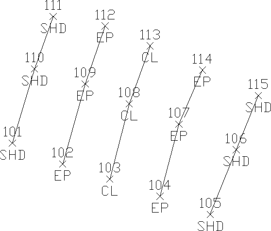
Resulting points and linework showing Zorro style template
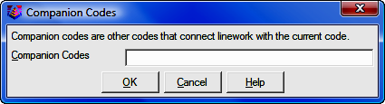
Companion Codes: This option allows different codes to connect when defined as line, polyline or 3d polyline. For example, a main line power pole code may be defined as PP while a service utility pole may be defined as UP. When processing Draw Field to Finish, it may be desired to connect all PP and UP codes together. This could be accomplished by defining a companion for UP as PP and a companion code for PP as UP. Each code needs to reference the other as a companion code.
Code: This is the key name that identities the code and is matched with the field data descriptions. It is important to note that the * character, used in this field, is regarded as a wildcard or "match anything" code. For example, a field code definition with the code defined as TREE* will be used for any raw description of TREE. Raw descriptions of TREEA, TREE12, TREE, etc. will match the TREE code definition. This will always be the case unless there is a more specific code is found. For example is there was a code TREEA in the code definition file, then that code would be used instead of the TREE code.
Full Name: This is an optional field that describes the code for viewing.
Point Group: This option is not currently utilized by "Sight" Survey.
Description: This value is assigned to the point description attribute when the point is drawn. This description can be different than the field description. An additional description can be added to a point by entering it after a forward slash in the data description field.
Use Raw Description: This option turns off the Description field described above. Instead the points will be drawn with their original unprocessed descriptions.
Main Layer: The point and line work for the code will be created in this layer.
Distinct Point Layer: When this toggle is selected, the line work is created in the layer defined in the Layer field and the points are created in the specified distinct point layer. For example, you could have DRIVEWAY for linework and DRIVEWAY_PNT for the points.
Dual 3D Polyline Layer: Displays the layer that the 3d polyline will drawn on when using an Entity Type of 3D and 2D. The layer name can be typed in this field.
Linetype: Line work can be drawn in any of the special linetypes or with the linetype for the layer ("BYLAYER"). The spacing and size of the special linetypes is determined by the AutoCAD LTSCALE system variable and by the field code settings Line Type Spacing Scaler and Line Type Text Scaler. The special linetype "hedge" is drawn with a user specified width. The special linetype "userdash" is drawn with user specified distances for the length of the dash and the length of the gap between dashes. You will be prompted for this information when you select that linetype.
Symbol: This is the point symbol for the code. To avoid drawing a symbol, use the Carlson symbol named SPT0.
Symbol Pts: For each code definition, the symbol insertion points can be defined with up to three points. To define the symbol insertion points, choose the [Symbol Pts] button in the Edit Code Definition dialog box. By default, the symbol insertion is defined by one point at the symbol center (0,0). A one point insertion definition can be used to insert a symbol offset from the center. With a two insertion point definitions, the program will rotate and scale the symbol. For example, two insertion points can be used to insert a tree symbol to size the tree, where the first point is for the tree center and the second is for the drip line. With three insertion point definitions, the program will rotate and scale the symbol in both X and Y. For example, three points can be used to insert a car symbol with the first point being the front drivers side, the second point as the back driver side (to rotate and scale the length) and the third as the back passenger side (to scale the width). Besides the insertion point coordinates, you can define a description for each point which is used for the drawn point description and is used for prompting in the Insert Multi-Point Symbol command and in Carlson Field data collection.
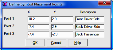
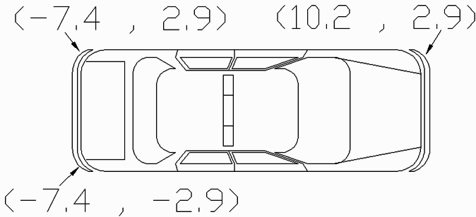
Three Point Symbol Drawing
The coordinates for the insertion point definitions are for the symbol at unit size. To figure these coordinates, you will need to open the symbol drawing (.DWG) file. By default, the symbols are located in the \Simplicity Sight Survey 2009\Symbol folder. For example to make an insertion point for the tree drip line, open the tree symbol drawing and find the coordinate at the edge of the tree symbol (in this case 0.5,0.0).
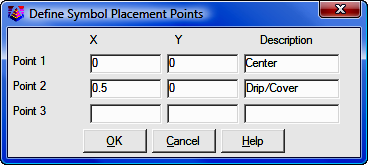
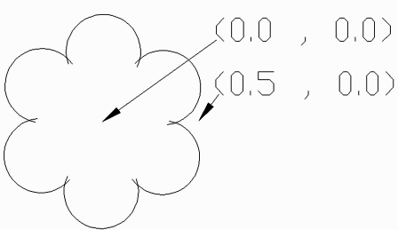
Two Point Symbol Drawing
Not all of the symbol insertion points need to be used when drawing
the points. If a code definition has a three insertion points, it is possible to
use just the first two or first one. There are special codes to associate
multiple points to the same symbol. The first code point is used as the first
symbol insertion point. The "2ND" code is used to specify the second symbol
insertion point. A point number can follow the "2ND" to identify a specific
point. Otherwise without the point number, the program will use the next point
with the current code. The "3RD" code is used to specify the third symbol
insertion point and similar to the "2ND" code, a point number after the "3RD" is
optional. The "2ND" and "3RD" codes should be assigned to the first point. For
example, consider a code of "CAR" with a three point symbol insertion
definition. If point #1 has a description of "CAR 2ND 3RD", then point #1 will
be used as the first symbol insertion point and the next two points with the
"CAR" description will be used as the second and third symbol insertion points.
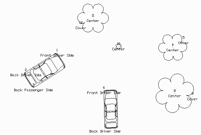
Multi-Point Symbol Drawing
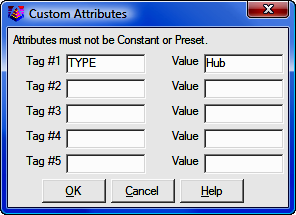
Custom Attributes: This feature allows you to use customized blocks that have customized attributes (the tag/value pairs). This feature works for both point attribute blocks and symbols. For attribute blocks, Field-to-Finish looks for attributes with the tags "PT#", "ELEV2", and "DESC2". The custom attributes feature allows you to define up to an additional 5 attributes in their custom blocks on a per-field code basis. For example, the custom block could have an attribute with the tag "TREE_SPECIES" and there's a separate field code for each species of tree. Each of those field codes can specify the value that should be assigned to the attribute that has the TREE_SPECIES tag. Then when the points are drawn, the tree species is shown. Note that the custom attributes must have their Constant and Preset properties set to "no". The custom attributes settings in F2F should not use those tags that the software already handles (PT#, ELEV2, and DESC2), or the setting will be ignored.
Set Color: The line work will be drawn in this color. The default is BYLAYER.
Text Size Scaler: This is a scaler value that is multiplied by the horizontal scale to obtain the actual size.
Symbol Size Scaler: This is a scaler value that is multiplied by the horizontal scale to obtain the actual size in AutoCAD. The horizontal scale can be set in CAD Configuration (CM - Section 5.03).
Line Width: This controls the width for the linework, and it only applies to 2D polylines.
Line Type Spacing Scaler: This is a scaler value that is multiplied by the AutoCAD LTSCALE system variable to give the distance between symbols in the line.
Line Type Text Scaler: This is a scaler value that is multiplied by the AutoCAD LTSCALE system variable to give the size of the text in a line.
Unit Symbol: This option will draw the point symbol at unit (1:1) scale. For example, this option could be used for a symbol that is already drawn to actual dimensions such as a car symbol.
Set Template: For 3D polyline codes, this option allows you to assign a template (.TPL) file to the code. The code points act as the centerline for the template and the program will drawn parallel 3D polylines for each break point (grade ID) in the template. The template file is defined in the Carlson Civil Design module, and is not used by "Sight" Survey.
Entity Type: This defines the line entity to be created. Points Only does not create any line work. 3D Polyline can be used for breaklines. 3D and 2D entity type selection creates a 3d polyline in the layer specified in the Dual 3d polyline layer setting and a 2d polyline in the layer identified in the Layer setting. Since 3d polylines do not display linetypes, this is useful when needing linework in 3d for design work while also needing to display linetypes for final plotting of the drawing. This provides an easy and quick way to turn off all 2d polylines or all 3d polylines by using the layer control dialog.
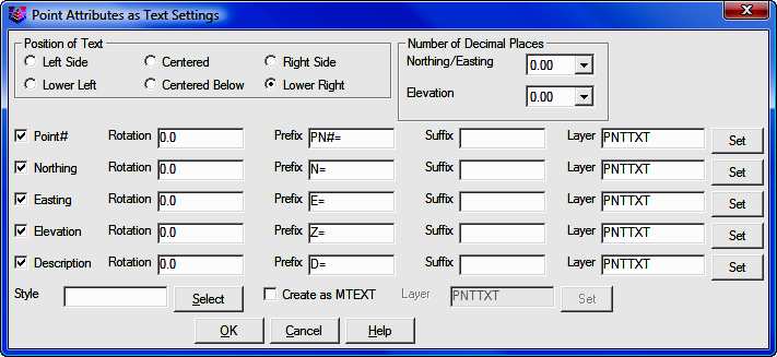
Attribute Format: This chooses the type of point entities to create. The Attribute Block format creates the Carlson point entity which is a block with attributes for point#, elevation and description. The Text Attribute format creates text entities for each of the point attributes. When the Text Attribute format is selected, the [Set] button is available where you can control which attributes to draw as text and the position, decimals, style, prefix, suffix and layer for each attribute.
Separate Attribute Layers: This controls the layers of the point and symbol attributes. With "None" the point layers are the standard layers, "PNTNO", "PNTELEV" and "PNTDESC", and the symbol layer is "PNTMARK". With "Points" or "Both" the point attribute layers begin with the layer for the code followed by the attribute type. For example, the "DWL" code shown in this dialog has a layer name "DRIVEWAY". The point attributes would then be "DRIVEWAYNO", "DRIVEWAYELEV" and "DRIVEWAYDESC". With "Symbols" or "Both" the symbol attribute layer begins with the layer for the code followed by "MARK".
Hard Breakline: This will tag the 3D polylines created with this code as hard breaklines. In Contour, (CI - Section 11.02) contours are not smoothed as they cross hard barriers.
Smooth Polyline: This applies a modified Bezier smoothing to the polyline. The smoothed polyline will pass through all the original points.
Connection Order: The points of a distinct code can be connected in their point number order or by nearest found which makes the line by adding the next closest point.
Tie: When checked the linework drawn with this code will always close. For example if you have points 1, 2, 3, and 4 with the code BLDG and Tie is checked on for the code BLDG, then the linework will be drawn from point 1 to 2 to 3 to 4 and then back to point 1, closing the figure.
Elevation Integers: This controls the number of digits to display to the left of the decimal point for the elevation label. The All setting will show the full elevation digits. The other settings allow you to limit the number of digits to display for the purpose of reducing the amount of space the elevation labels take up in the drawing. For example, if a site is in the 4000 foot elevation range, then this setting could be set to three digits (000) and an elevation of 4321 would be labeled as 321.
Elevation Decimals: This controls the display precision for the elevation label.
Elevation Prefix/Suffix: These set the prefix and suffix for the elevation label per code. In the Draw function under Additional Draw Settings, there is an override to set the elevation prefix/suffix for all the codes.
Attribute Layout ID: Controls the location of the point number, elevation and description. These attribute layouts are defined in AutoCAD drawings that are stored in the Carlson SUP directory with the file name of SRVPNO plus the ID number (i.e. SRVPNO1.DWG, SRVPNO2.DWG, etc.). If you want to change the attribute positions for a layout ID, then open and edit the associated SRVPNO drawing.
Locate Pts on Real Z Axis: This option will draw the points at the actual point elevation. Otherwise the points are drawn at zero elevation. For example, you could turn this option off for the FH for fire hydrant code to drawn them at zero. Then the GND code could have this option on to draw the ground shots at their elevations.
Random Rotate: This option will randomly rotate the symbol. For example, this option could be used for tree symbols to have the trees drawn in various orientations.
Rotate to Line: This option applies to points that are part of Field-to-Finish linework. This option will align the point attributes and symbol to the associated linework.
(Field to Finish) dialog continued...
Select All: This option selects all the codes. This can be used when only wanting to process a couple of codes. For example, use the select all option to select all the codes and then turn them off. Now select the codes for processing and turn them on. Also it can be used to make a global change to all the codes.
Add: The new code definition is inserted in the list in the position after the currently selected one. If none are selected for positioning, the new code is placed at the top. Only one code definition may be highlighted before running this routine.
Copy: This option copies the definition of a selected code. It opens the Edit Field Code Definition dialog and copies the definition of the selected code to the appropriate settings. It does not copy the name of the code. It is a time saving tool to use when creating codes that are similar with only a couple of differences.
Cut: This command will remove the highlighted code definitions from the list and puts them in a buffer for retrieval with Paste.
Paste: This command will insert the code definitions put in the buffer by the Cut command. These codes will be inserted after the row of the currently highlighted code or at the top.
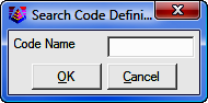
Search: Allows you to search for a specific code in the list.
Process
Draw: This command returns to the Draw Field to Finish dialog box.
PointCAD Coding
Field-to-Finish supports an early Carlson style of linework coding called
PointCAD. The PointCAD codes use numbers with +,-,* symbols as follows:
+0 Starts a regular 2D line (not a polyline) that is open.
*0 Starts a regular 2D line that is closed.
+4 Starts a curved 2D polyline that is open.
*4 Starts a curved 2D polyline that is closed.
+1 Begins a 3-point arc.
-0 or -1 or -3 or -4 or -5 or -6 or -7 Ends a line.
+5 Starts a 3D polyline that is open.
*5 Starts a 3D polyline that is closed.
+6 Starts a 2D polyline that is open.
*6 Starts a 2D polyline that is closed.
+7 starts line whose type (2D line, 2D polyline, 3D polyline) is specified
by the point's field code definition. If the field code definition is to use
points, then a 2D line is started.
+2 Middle point of 3 point arc
-05 starts a curved 3D polyline section.
-50 ends a curved 3D polyline section.
+8 starts a 2D and 3D polyline combination that is open.
*8 starts a 2D and 3D polyline combination that is closed.
-8 ends a 2D and 3D polyline combination.
-08 starts a 2D and 3D polyline combination curve that is open.
-80 reverts back to a straight 2D and 3D polyline combination.
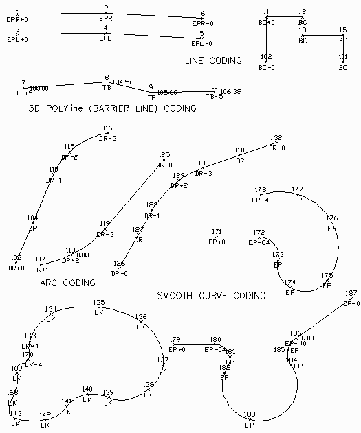
PointCAD linework coding examples