The COGO menu is found next to the Draw menu in MAP view. Below you will find each feature described.
Inverse (I):
Inverses and presents the bearing and distance between point numbers. Has the added benefit that the previous point inversed becomes the backsight, and the current point inversed becomes the occupied point, allowing you to sequence directly into the Traverse or Sideshot commands. (Use angle code 7 to turn an angle right from the backsight to the foresight.)
![]()
Traverse (T) (also TR):
Similar to the Sideshot command, the Traverse command will “move up” to the last point traversed, holding the previous occupied points as the backsight. Exit with Esc.
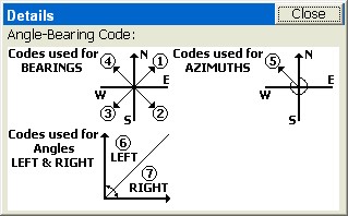
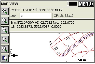
Sideshot (SS) (also S): This allows for sideshots from any point that is “occupied” by use of the inverse command. For example, if you inverse from 126 to 150, you are “on” 150 and backsighting 126. Then at the prompt: Cmd: Inverse – Tr/Ss/Pick point or point No: You can enter S for Sideshot. The first prompt is the Angle-Bearing Code: Sideshot-eXit/I/Tr/H/Angle-BC(1-7)<7>, which can be any of the following:
1-NE (0 through 90 if degrees, 0 through 100 if gons/grads)
2-SE (same as above)
3-SW (same as above)
4-NW (same as above)
5-Azimuth (360 circle if degrees, 400 circle if gons/grads)
6-Angle Left (degrees or gons)
7-Angle Right (degrees or gons)
Note that at the Angle/Bearing prompt, you can transition back to inverse (from your occupied point) or to traverse, which would move you up to the next traversed point. Within Sideshot, you stay on your current point, holding the backsight, and foresighting (calculating) as many points as desired. X returns to the MAP screen as does Esc.
The remaining prompts are the angle itself (as in 85.3522, DDD.MMSS), zenith angle, slope distance, description and point number. Exit with Esc anytime. In gons/grads, angles are also in decimal form, and angles such as 397.9871 are valid.
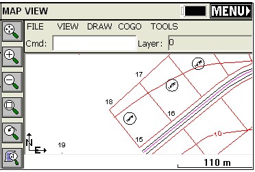
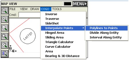
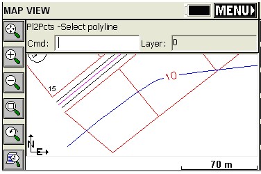
Interpolate Points - Polyline to Points (P2P):
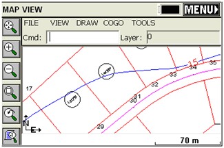
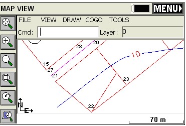
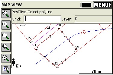
This command converts any selected polylines into points. It is useful in capturing points for stakeout from polylines created as offsets or brought in from DXF files. This allows you to react to circumstances in the field by creating points from polylines, when and where needed. For example, if you wanted to make point numbers out of the lot corners below on the SW lot, Select Cogo, Interpolate Points, Polyline to Points (or more simply enter P2P at the command line). Then pick each desired polyline. The program will avoid making duplicated points on vertices that already have point IDs.
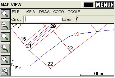
The new points are shown in “large” format, for emphasis.
Interpolate Points - Divide Along Entity (DVS):
This divides a polyline into the number of segments entered. A dialog will allow you enter in the number of segments. There are settings to prompt for descriptions and elevations and to create points at the endpoints of the polyline.
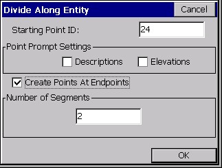
The command will create new vertices along the polyline, but can also create point numbers starting at the entered Point ID, and you can elect to be prompted for descriptions and/or elevations at each new point. If a property line were divided into two segments, you would create three new points.

Interpolate Points - Interval Along Entity (DVI):
This divides a polyline by the distance entered in. Curves can have a different interval. There are settings to prompt for descriptions and elevations and to create points at the endpoints of the polyline.
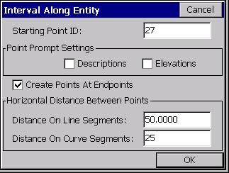
This command is often used for creating points on centerlines. Note the the program resets the interval at break points like PI’s and PC’s.
Hinged Area (HA):
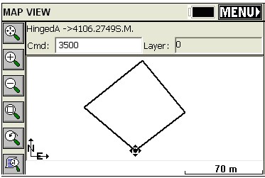
This command can be used to determine the dimensions of a figure when the area is fixed and three or more sides are known. The figure must be defined by a closed polyline. After executing the command, select the polyline. Next, select the hinge point, the polyline segment clockwise from your hinge point will be the segment to move. SurvCE will then ask you if you want to keep the existing polyline. If you answer Yes, a new polyline with the desired area is created, if you answer No, the polyline you pick is modified. Next, the current area of the polyline is shown. At this point, enter the new area in the units specified under Job Settings. (If your units are set to feet, the area will be specified in square feet). See the top figure below.
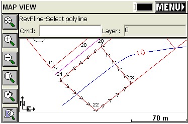
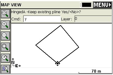
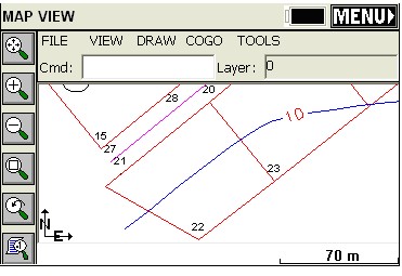
Note how the hinged side occurred on the clockwise side of the polygon perimeter (side 22 to 23). If we erase the new polyline, reverse the original polyline (RV) and repeat the command, this time answering “No” to “Keep existing” and targeting 4500 s.m. area, we get the following:
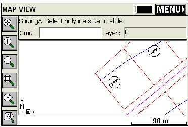
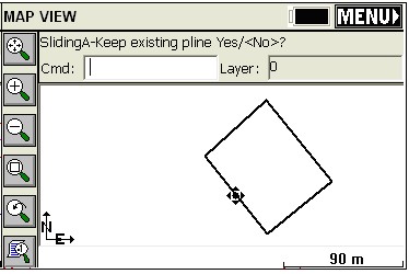
Sliding Area (SA):
This command adjusts one side of a polyline to meet a specified area. You must specify the new area in the same units as specified under Job Settings. The area to adjust must be a closed polyline. After executing the command, select the polyline. SurvCE will then ask you if you want to keep the existing polyline. If you answer Yes, a new polyline with the desired area is created, if you answer No, the polyline you pick is modified. Next, the current area of the polyline is shown. At this point, enter the new area in the units specified under Job Settings. (If your units are set to feet, the area will be specified in square feet).
Triangle Calculator (TC):
Goes directly from the MAP view to the Triangle calculator. See COGO - Calculator for detail.
Curve Calculator (CC):
Shortcut to the curve calculator, then returns to MAP. See COGO - Calculator for detail.
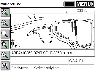
Area (AR):
This will report the area of any picked polyline. If you pick an unclosed polyline, the program will draw a temporary line for the closing segment and report the area.
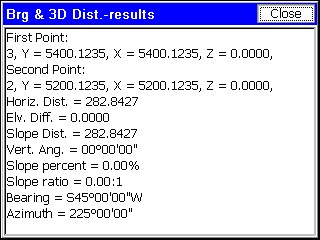
Bearing & 3D Distance (3D):
This command reports the horizontal distance, elevation difference, slope distance, vertical angle, percent slope, slope ratio, bearing and azimuth between two 3D points. The user can pick or enter the number of two points, select a polyline segment or pick two points on any polylines from MAP.