
Tools Menu:
Surface11.02 Contour (CI)
FUNCTION: The Contour
routine is used to create and label contours. This routine is also capable of creating a TIN surface file.
Activate the Contour routine by picking from the Tools menu; by pressing [Alt][T], [S], [C]; or by typing the two-letter command CI at any data entry prompt. You may also enter the Contour routine from within the Point Manager (PM - Section 6.09) by first selecting your points and clicking the [Contour] button.
The Contour window is a multi-purpose dialog box. Using this single screen you can:
Create a Contour using Points, while specifying the contour line color, layer, type, weight and the contour interval.
Create a Contour using a Surface File, while specifying the contour line color, layer, type, weight and the contour interval.
Specify Breaklines, Inclusion and Exclusion perimeters (by layer)
Draw Breaklines, Inclusion and Exclusion perimeters
Draw Index Contours, while specifying the contour line color, layer, type, weight and the contour interval.
Erase Previous Contours
Draw Surface Triangles, while specifying the triangle line color and layer.
Erase Previous Triangles
Construct a Surface File
Label Contour Lines, while specifying the text color, layer, text font, text size, and label precision.
Activate the Calculate Volume routine (CV - Section 11.06)
Contour Construction Parameters
The top section of the dialog contains the basic parameters for contour construction. Here you will specify Contours by Points or Contours by Surface; Breakline Layer(s); Inclusion Areas; and Exclusion Areas.
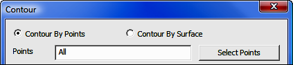
Contour By Points: Select this option to construct contours by using points. Enter the Points (numbers or ranges), or click [Select Points] to select points using the Point Manager (PM - Section 6.09).
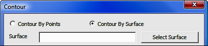
Contour By Surface: Select this option to construct contours by using a surface file. Enter the Surface or click [Select Surface] to select points from the Select Surface dialog (see below).
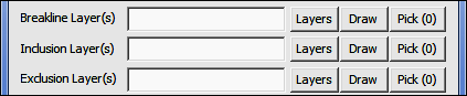
Breakline, Inclusion, and Exclusion Layers: Breaklines, Inclusion and Exclusion perimeters are defined as 2D or 3D-Polylines on specified layers.
|
|
WHAT THEY ARE: Breaklines, Inclusion Perimeters, and Exclusion Perimeters
Breaklines:
Breaklines are line segments that have the ability to modify the surface
model by locally adjusting the triangulation. Breaklines are helpful
for defining objects such as building slabs, retaining walls, grade lines,
ditch bottoms, roadbeds, etc. Breaklines may consist of segments and
do not have to be closed polylines. You may specify multiple
breaklines. Inclusion Perimeters:
If an Inclusion Perimeter is specified, "Sight" Survey
will generate contours only within the specified perimeter, regardless of
number of points in the data set. You may specify multiple
inclusion perimeters. You may not specify inclusion
perimeters that lie within an exclusion perimeter. Exclusion
Perimeter: If an Exclusion Perimeter is specified,
"Sight" Survey will not generate contours within the specified
perimeter. You may specify multiple inclusion
perimeters. You may also specify an exclusion perimeter that
lies within an inclusion perimeter.
|
Select or enter the layer(s), or click [Select Layer(s)]
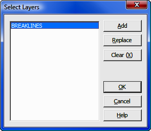
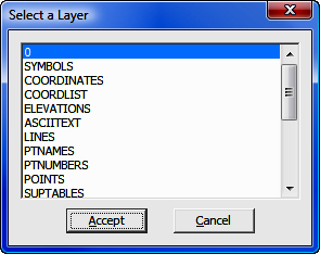
The Select Layers dialog shows the layer(s) designated to contain breaklines. Clicking on [Add] or [Replace] will display a Select a Layer dialog box showing a complete listing of the active layers in the drawing. This is your "select from" list.
To Add a layer, click [Add] and pick a layer from the Select a Layer list that appears, then click [Accept].
To Replace a layer, select the layer you want to replace, then click [Replace] and pick a layer from the layer list that appears, then click [Accept]. You may elect to replace multiple layers with a single layer selection. To select multiple layers in the Select Layer dialog, simply click on each layer you want to select.
To Clear the entire list, click [Clear (X)].
When you have completed your layer selections, click [OK].
[Draw]: This button activates the Draw Polyline routine (DP - Section 12.32). Use this routine to easily construct breaklines, inclusion perimeters, and exclusion perimeters.
Any polyline drawn for use as an inclusion or exclusion area must be a closed polyline.
[Pick (0)]: Select this button to pick the polyline from the drawing. You may pick more than one polyline, and the number in parentheses on the button face indicates the number of selected polylines.
In AutoCAD or IntelliCAD, end the selection process by pressing [Enter] or [Space Bar]. To clear your selections, right-click the [Pick (1)] button. To end the selection process without selecting a polyline, press [Esc].
In MicroStation, end the selection process by double-right-clicking your mouse. To clear your selections, right-click the button. To end the selection process without selecting a polyline, double-right-click your mouse to return to the Contour dialog, then right-click the [Pick (1)] button.
|
|
IMPORTANT: Inclusion and Exclusion perimeters must be closed polylines or contouring errors will occur. When entering a point string you do not have to conclude the string with the starting point number unless the the last point number listed is a point on a curve. In that case, the ending point and starting point must match. |
This section of the Contour dialog contains the settings used to draw the contour lines.
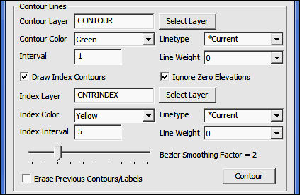
Contour Layer: Enter the name of a layer upon which the contours will be drawn, or click [Select Layer] to pick one of the active layers. If you enter a name of a layer that is not currently in the drawing, that layer will be created.
Contour Color: Select a contour color from the drop-down list by clicking [q]. The selection list contains 16 basic colors. If you want to use a different color or color palette, use the Edit Layers/Levels routine (LA - Section 4.05) to set the contour layer color, then for Contour Color use the By Layer setting.
Linetype: Select an contour linetype from the drop-down list by clicking [q]. The list will contain linetypes currently in the drawing.
Interval: Enter the contour interval.
Line Weight: Select a contour linetype from the drop-down list by clicking [q].
Draw Index Contours: Select this option if you want to include Index Contours in your drawing.
Ignore Zero Elevations: Select this option to disregard any points in the selection set that have a zero elevation.
Index Layer: Enter the name of a layer upon which the index contours will be drawn, or click [Select Layer] to pick one of the active layers. If you enter a name of a layer that is not currently in the drawing, that layer will be created.
Index Color: Select an index contour color from the drop-down list by clicking [q]. The selection list contains 16 basic colors. If you want to use a different color or color palette, use the Edit Layers/Levels routine (LA - Section 4.05) to set the index layer color, then for Index Color use the By Layer setting.
Linetype: Select an index contour linetype from the drop-down list by clicking [q]. The list will contain linetypes currently in the drawing.
Index Interval: Enter the index contour interval.
Bezier Smoothing Factor: This factor controls the amount of smoothing of the contour lines. Typically, less is better. High amounts of smoothing may cause "looping" of some contour lines. Too adjust smoothing, grab the slider (left-click and hold your mouse button down) on the slider and move it to the desired position. You mal also click on the scale bar either to the left or right of the slider to move the slider one step at a time.
Erase Previous Contours/Labels: Select this option to erase any previous contours and labels from the drawing before drawing new contours.
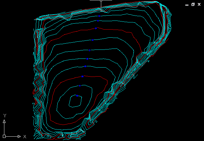
[Contour]: Click this button to draw the contours and/or create a surface file. A completed contour map example with labels is shown below the Label section. Triangles were not drawn.
|
|
HINT: If you want to construct a surface file and create contours at the same time, complete the Surface portion of the Contour dialog (See below) before clicking [Contour]. |
Surface
This section of the Contour dialog contains the settings used to create a surface file.
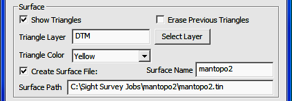
Show Triangles: Select this option to draw the surface triangles.
Erase Previous Triangles: Select this option to erase any previous triangles from the drawing before drawing new triangles.
Triangle Layer: Enter the name of a layer upon which the surface triangles will be drawn, or click [Select Layer] to pick one of the active layers. If you enter a name of a layer that is not currently in the drawing, that layer will be created.
Triangle Color: Select a triangle color from the drop-down list by clicking [q]. The selection list contains 16 basic colors. If you want to use a different color or color palette, use the Edit Layers/Levels routine (LA - Section 4.05) to set the triangle layer color, then for Triangle Color use the By Layer setting.
Create Surface File: Select this option to create a surface file during the contouring operation.
Surface Name: Enter a name for your surface. This is the name that will be shown on the list of available surfaces.
Surface Path: Enter a location for the surface file. The default location is in the current job folder, using the surface name (.tin) as the filename. Your filename does not have to match your surface name.
|
|
HINT: Surface file construction occurs when you click [Contour]. You can also create surfaces using the Surface Manager (SM - Section 11.01), within the View Triangles routine (VT - Section 11.03), or within the Calculate Volume routine (CV - Section 11.06). |
This section of the Contour dialog contains the settings used to label the contour lines.
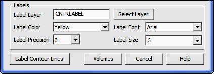
Label Layer: Enter the name of a layer upon which the contour labels will be written, or click [Select Layer] to pick one of the active layers. If you enter a name of a layer that is not currently in the drawing, that layer will be created.
Label Color: Select a label text color from the drop-down list by clicking [
q].
Label Font: Select a label text font from the drop-down list by clicking [q].
Label Precision: Select a label precision from the drop-down list by clicking [q]. Label precision is the number of decimal places you want showing on your contour labels.
Label Size: Select a label size from the drop-down list by clicking [q].
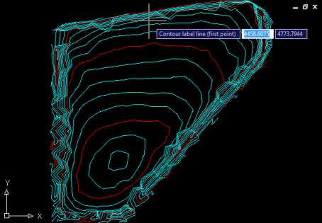
[Label Contour Lines]: Click this button to label contours; control will switch to the CAD window. Label locations are determined by a line you strike across the contour lines in the CAD window. You will be prompted (in CAD): Contour Label Line (first point). Click a starting position.
CAD then prompts: Contour label line (second point). Stretch the rubber-banded line across the contour lines until it is in the position you want to apply labels, then click.
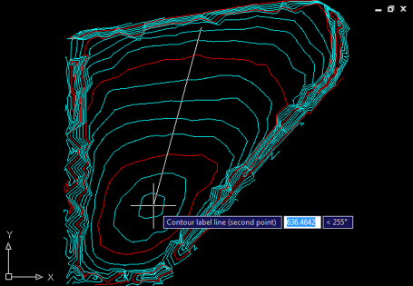
Contour labels are drawn along the line's position as it intersects with each contour line.
Select Surface
If you are selecting a surface, a dialog box will appear with the available surfaces. You may choose one of the surfaces shown and click [Use this Surface] which will insert the file name into the Surface Name field in the main dialog.
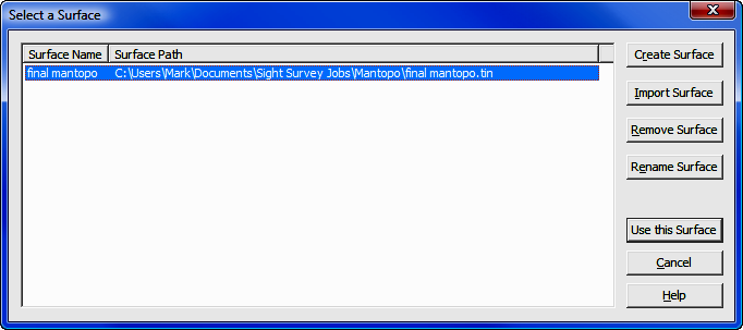
Using this dialog it is also possible to [Create Surface], [Import Surface], [Remove Surface], or [Rename Surface].
[Remove Surface]: Clicking this button removes the highlighted file from the list. The file is not deleted, simply removed from the selection list. To actually delete a surface file, use Windows Explorer (My Computer).
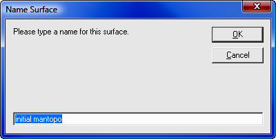
[Rename Surface]: Clicking this button will allow you to rename a surface for ease in identification. Renaming only affects the selection list, not the file itself. In other words, when looking at the Select a Surface dialog box, the Surface Name changes, but the Surface Path (or original file name) does not.
[Create Surface]: This feature is described below.
[Import Surface]: This feature is described following the Create Surface section.
Create Surface
Click [Create Surface] to build a new surface.
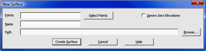
Points: Enter the point numbers (or ranges) that will be used to construct the new surface. Click [Select Points] to select points using the Point Manager (PM - Section 6.09).
Ignore Zero Elevations: Select this option to disregard any points in the selection set that have a zero elevation.
Name: Enter a name for the surface. This name will appear in the Select a Surface dialog and while it does not have to match the actual surface file name, it will appear along with the Path in the next data entry field.
|
|
HINT: If you intend to change the path, DO NOT press [Enter] after entering the file name. Press [Tab] or click into the Path field. Pressing [Enter] is the same as clicking [Create Surface]. |
Path: By default, the path will set to the folder for the current job, and the actual name of the surface file will default to the Name specified above. If you want the actual file name to be something different, you may edit the Path line. To select a different path, click [Browse]. After entering a path, press [Enter] or click [Create Surface].
[Create Surface]: Click this button to create the surface. The New Surface dialog closes and you are returned to the Select a Surface dialog, where your new surface will appear on the surface selection list. To use the newly created surface, click [Use this Surface].
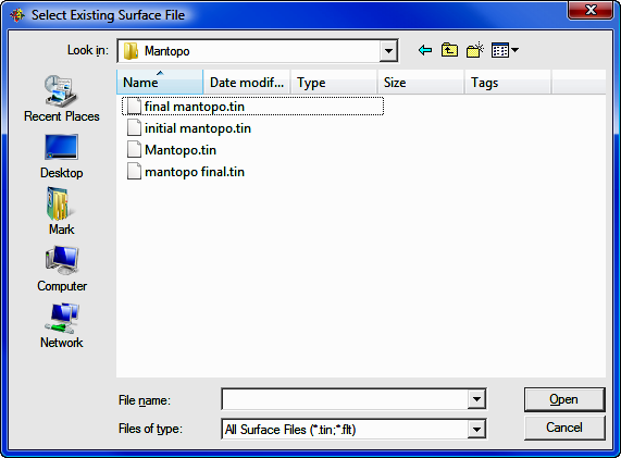
Import Surface
Using a standard Windows file selection dialog, select an existing Surface file to import and click [Open]. The file selection dialog will close and the selected file will be imported to the Select a Surface dialog.
After selecting the file to import, you may give the surface a more descriptive name that will appear on the selection list. Renaming only affects the selection list, not the file itself. In other words, when looking at the Select a Surface dialog box, the Surface Name changes, but the Surface Path (or original file name) does not.