Draw Menu: Elements
12.32 Draw Polyline (PL)
FUNCTION: The Draw Polyline
routine is used to create a continuous polyline (AutoCAD/IntelliCAD) or line string (MicroStation). Curves may be contained in 2D-Polylines (AutoCAD/IntelliCAD) and also in MicroStation. Annotation may also be included. Polylines may be used to indicate breaklines, and closed polylines may be used to designate inclusion and exclusion perimeters (see Contour - Section 11.02).
Activate the Draw Polyline routine by picking from the Draw > Elements menu; by pressing [Alt][D], [M], [P]; or by typing the two-letter command PL at any data entry prompt. This routine may also be activated from within the Contour routine (CI - Section 11.02) by clicking on any of the three [Draw] buttons adjacent to the layer settings for Breaklines, Inclusion, and Exclusion perimeters.
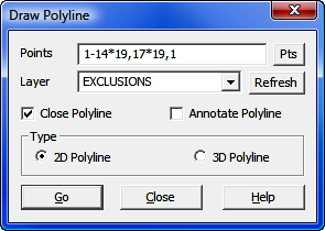
Points: Enter a point string in accordance with the rules listed below. You must enter a point string; this routine does not accept individual points. You may enter DF to use a figure from your list of Defined Figures (Section 6.20). You
|
|
TIP: Left-click the [Pts] button to select a point from the Point Manager (PM - Section 6.09). Right-click the [Pts] button to select a point from the CAD window (see Picking Points in CAD in Section 2.03). Points selected from the CAD window will be added to the point string in the Points field. |
Layer: Enter the name of the layer upon which the polyline will be placed, or click [q] to select from a list of available layers. If you enter the name of a layer that is not currently in the drawing, it will be created.
[Refresh]: Click [Refresh] to refresh the layer list from the drawing. If you have manually added layers to your drawing using only CAD commands (commands not initiated from within "Sight" Survey), you should issue the [Refresh] command to incorporate those layers into "Sight" Survey.
Close Polyline: If you are constructing an Inclusion perimeter or Exclusion perimeter for use in contouring, you must select the Close Polyline option. Open polylines used for inclusion or exclusion perimeters will result in incorrect contouring. In the figure shown above, selecting the Close Polyline option will automatically close the polyline from point 11 back to point 1.
Annotate Polyline: Choose this option if you wish to have bearing and/or distance annotation placed on your polyline. The annotation is placed on the layer selected to contain the polyline using the Text Font, Text Size, Text Placement, and Text Color properties as set on the Drawing Properties menu (PR - Section 5.10).
Type: Select the type of polyline to be drawn; either a 2D Polyline, or a 3D Polyline. Either type is sufficient for breaklines, inclusion perimeters, and exclusion perimeters. 2D Polylines may contain curves, while 3D polylines may not.
[Go]: Click [Go] to draw the polyline on the specified layer using the Object (Line) Color, Line Type, Line Weight, and Line Type Scale as set on the Drawing Properties menu (PR - Section 5.10). The Draw Polyline routine remains available to draw additional polylines. Click [Close] to exit the routine.
|
|
RULES FOR POINT STRINGS: 1. Separate single points by a comma, for example: 1,3,5,7 2. Separate a consecutive range of numeric point numbers by a dash, for example: 1-7 3. Enter all alphanumeric point numbers individually and separate them by a comma, for example: PT1,PT3,PC8,NCorL1 4. Preface any radius points with an asterisk (*) or less than size (<) for acute curves or a greater than sign (>) for obtuse curves, and use only the *, <, or > to separate the PC and the radius point of a curve; for example 5*10,8 sets the acute curve from 5 through center point 10 to end point 8; and 5>10,8 sets the obtuse curve from 5 through center point 10 to end point 8. Don’t place a comma after the 5. 5. Curve points may be entered within point ranges, if desired. For example: 1-7*8,10*8,15*8-17,1 is the same as entering points 1-7*8-10*8,15*8,16*8,17,1. 6. DO NOT start your point string with a radius point (*, >, or <) designation. 7. Use care when entering your point string since the program will not attempt to screen your entry for illegal characters or unassigned points. |