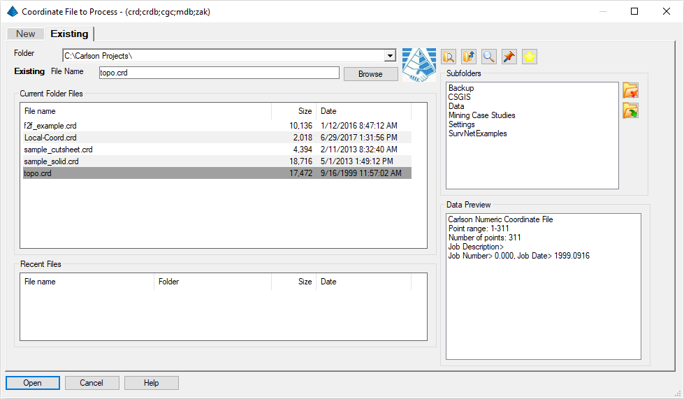
- If you get the Start Page, pick New Drawing.
- If you get the Startup Wizard dialog box, click the Exit button.
- If you are taken directly into CAD, continue as is.
NOTE: Many of the routines below can also be accomplished with the Carlson Survey and/or Construction modules but our focus herein will presume use of the Civil module.
Next, issue the Points -- Draw-Locate Points command which displays the dialog box similar to that shown below:
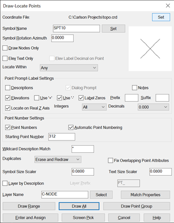
Choose Symbol "SPT0" by clicking Set to the right of Symbol Name then picking Symbol SPT0 from the options that appear. Establish the other settings as shown above and then click the Draw All button.
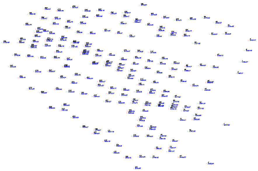
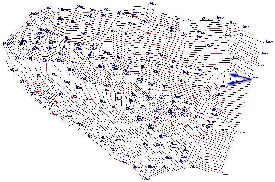
The points immediately plot on the screen, and the program should zoom to the extents of the points. If you don't see the points, issue the View -- Extents command. Your drawing should resemble that shown below (drawn with a horizontal plot scale factor of 50 as established in Settings -- Drawing Setup):
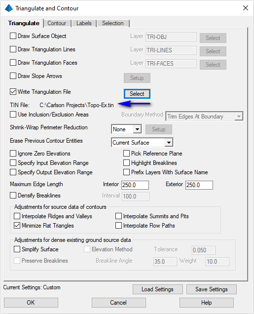
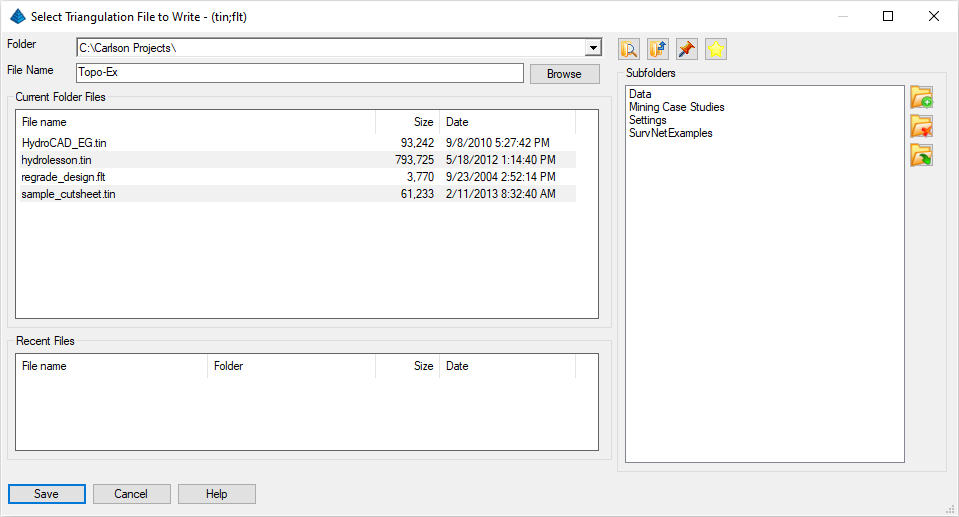
- In the Triangulate tab (as shown above), enable the
Write Triangulation File toggle and click its
Select button to set the name of a triangulation
(*.tin) file as illustrated below. Click the Save
button on this dialog box so that the results of the triangulation
can be re-used for future purposes. Set the Maximum Edge
Length values to 250 in all cases. If the goal of the
field crew was never to shoot points further apart than 100 feet,
then certainly triangulation lengths over 250 feet (or less) can be
ignored. Set the Shrink-Wrap Perimeter Reduction
to None (again, as illustrated above):
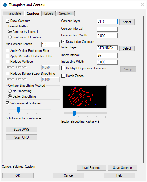
- In the Contour tab, as shown below, set the
Contour Interval to 5, turn on Draw Index
Contours and set its interval to 25 (index intervals are
most often 5 times the standard contour interval):
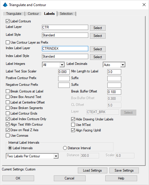
- In the Labels tab, as shown below, enable the
Label Index Contours Only toggle. Also set the
Layers for the Intermediate and Index contour labels to be the same
as that for the contours themselves:
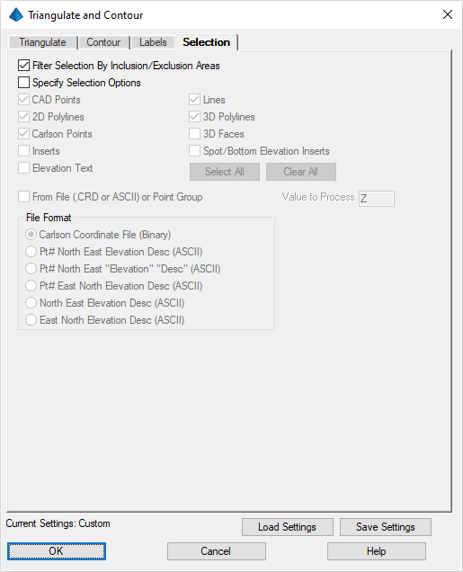
- In the Selection tab, as shown below, clear the
Specify Selection Options toggle:
Select points and breaklines to Triangulate.
[FILter]/<Select entities>: type ALL and press Enter twice
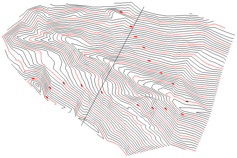
A "TIN" file is written and the contours are drawn. Here is the plot so far:
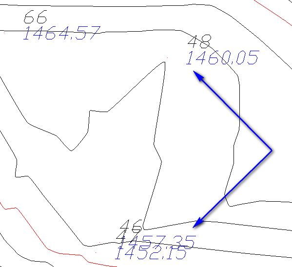
While some may prefer to directly change the contours (e.g. through the Surface -- Modify Contours -- Edit Contours command), we'll simply instruct Carlson to ignore the point for the purposes of contributing to a TIN.
"Double-click" (two left-mouse clicks in rapid succession) on Point 46 which will display the Edit Point Attributes dialog box (which can also be found under Points -- Edit Point Attributes) as shown below:
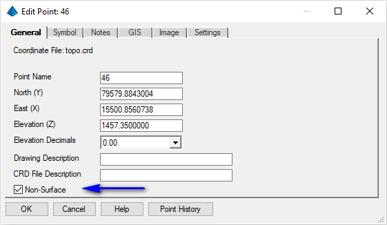
Simply enable the Non-Surface option as shown above and click OK. This is essentially the same as using the 3D Data -- Non-Surface Points/Entities -- Tag Non-Surface Points command.
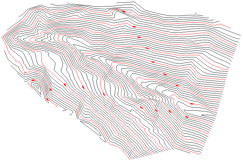
Also double-click on Point 48 to set its Non-Surface setting. When done, re-issue the Surface -- Triangulate & Contour using the exact same settings and sequence as cited above. Issue the View -- Freeze Layer by Selection and pick on one of the points (its number or its elevation), and press Enter. The points freeze. The results are below:
Tip: Whenever you make Carlson files, such as coordinate files (crd), TIN files (tin), and even pond capacity files (cap), they store to disk. When you do an Undo command (U for undo), you undo the graphics, but the files are safely stored and are not undone. Carlson does not like to overdo making files. Make them if you want, but we will not make any that are not needed.
When prompted:
[Continue/Extend/Follow/Options/<Pick point or point numbers>]: pick the southerly starting location
[Arc/Close/Distance/Follow/Undo/<Pick point or point numbers>]: pick the northerly ending location
[Arc/Close/Distance/Extend/Follow/Line/Undo/<Pick point or point numbers>]: press Enter to terminate the command
When prompted:
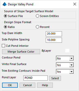
Pick top of pond polyline: pick the polyline as drawn earlier
Select the TIN file Topo-Ex.tin created earlier and then click Open.
Pick point within pond: pick upstream (northwesterly) of the polyline
Outslope ratio <2.00>: type 3 and press Enter
Interior slope ratio <3.00>: type 4 and press Enter
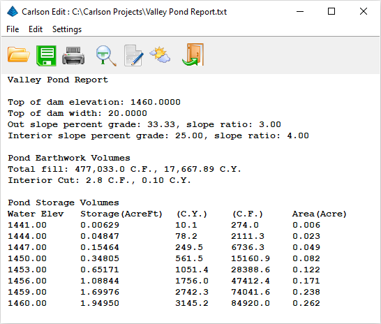
Range of existing elevations along dam top: 1420.63 to 1572.11
Top of dam elevation: type 1460 and press Enter
Calculate stage-storage values [<Yes>/No]? type Y and press Enter
Method to specify storage elevations [<Automatic>/Interval/Manual]? press Enter
The following report includes earthwork volumes and water storage volumes (your report will be slightly different):
Click the Exit (Doorway) button to continue forward in the process:
Output dam merged with existing or dam only [Merge/<Dam>]? press Enter and save the surface of just the dam in the file Topo-D.tin (for Topo with Dam)
Write stage-storage file [Yes/<No>]? type Y and press Enter to create a Topo-D.cap file
Adjust parameters and redesign pond [Yes/<No>]? type N and press Enter
Retain trimmed polyline segments [Yes/<No>]? type N and press Enter
Contour the pond [<Yes>/No]? type N and press Enter
The process is complete. At the Command line, enter E (for Erase) and when prompted:
[FILter]/<Select entities to delete>: pick on the centerline of the dam (there might be two of them)
[FILter]/<Select entities>: press Enter
Tip: The stage-storage curve that you save will plot in the Carlson Hydrology program. It makes a nice, handy plot for report purposes. See Tutorial - Hydrology and Watershed Analysis. Let's save the drawing through the File -- Save and name the drawing Topo-D.dwg.
Select entities for the scene.
[FILter]/<Select entities>: type ALL and press Enter
[FILter]/<Select entities>: press Enter
This leads to the starter view (a plan view) shown below:
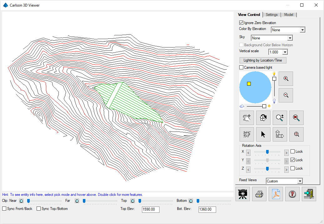
The main trick is to move the X-Axis bar to the left. Avoid the Y-Axis dial for now, and then grip on the Z-Axis dial and move it back and forth relatively fast, or just click on the Z-Axis arrows and watch things move slower. It's like you are in a helicopter over the site. Here's an example:
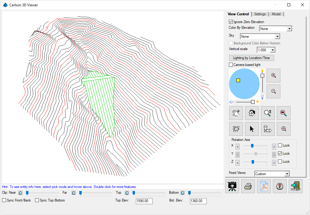
Click the Exit (Doorway) button to dismiss the 3D Viewer dialog box.
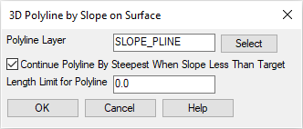
Complete the values as shown above and click OK. When prompted: Choose a Grid or Triangulation File specify the Topo-Ex.tin file created earlier
Pick origin point of 3D polyline: pick a point on the south side of the top of the dam, just before it contacts the ground as shown above
Direction of 3D polyline [<Up>/Down]? D
Direction of 3D polyline facing down slope [<Left>/Right]? R
Slope format [<Percent>/Ratio/Degree]? press Enter
Enter design slope percent: 10 (the values below should be similar to your results)
Horizontal distance: 415.34, Slope distance: 417.41
Vertical drop: 41.53, Avg slope: 10.00%, Max slope: 10.00%
Adjust slope [Yes/<No>]? N
Pick origin point of 3D polyline (Enter to end): press Enter
This created a smooth, 10% downhill grade 3D polyline which we can use to construct a maintenance road to service the dam.
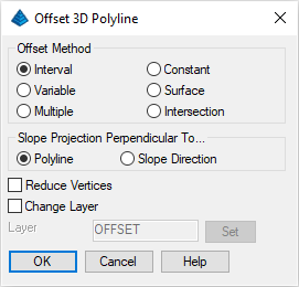
This is a Carlson specialty; a high-powered Civil Design feature. In short, you can work in 3D because you can offset and manipulate 3D polylines using Carlson. Set the values shown in the dialog box above and click OK. When prompted:
Vertical/<Horizontal offset amount>: 30 (for a 30' wide road)
Percent/Degree/Ratio/Vertical offset amount <0>: press Enter for a zero vertical offset from the original
Select a polyline to offset: pick our new 3D polyline
Select side to offset [Both]: pick into the hill (to the left or southwesterly)
Select a polyline to offset (Enter to end): press Enter
This creates the other side of the road parallel, but not joined yet.
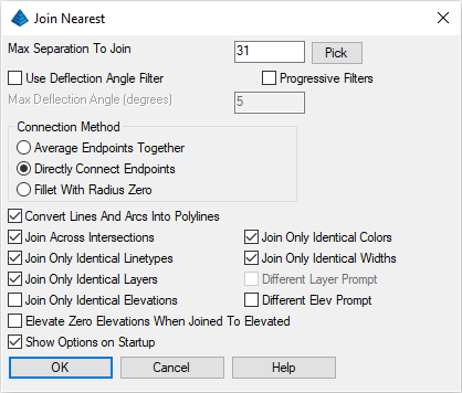
Because the two polylines are 30' apart, specify the Max. Separation to Join value to be 31. That way, they will join! The most important aspect is to specify the Directly Connect Endpoints option. Click OK. When prompted:
Select lines, arcs and unclosed polylines to join [Settings].
Select entities: pick both sides of the road one at a time, carefully avoiding picking a contour and press Enter when complete
NOTE: If a contour is picked, press the Esc key to exit the command and start over or use Selection options (e.g. press R for remove, pick it to remove it from the selection set, then A to Add, and pick again on the road) to build the proper selection set.
Tip: This may be obvious, but when it is difficult to pick what you want (e.g. because several objects are nearby or are over top of what you want), it pays to do View -- Window and zoom in closer, followed by View -- Previous after you are done.
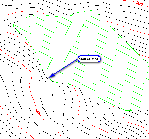
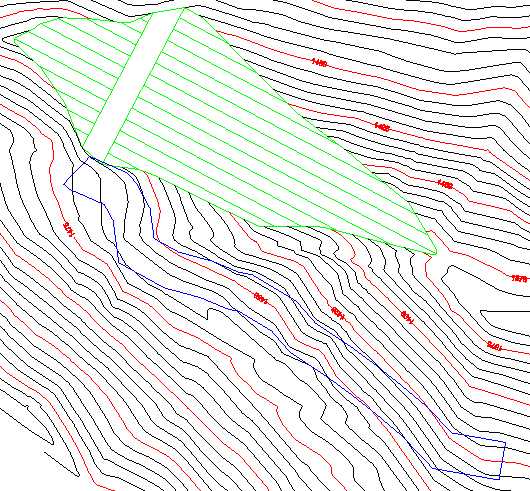
We have a road, or at least a sloping pad, seen below:
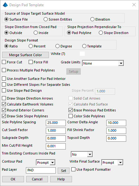
Design Pad Template is one of the more diverse and powerful commands in Carlson. We will use it here to make a simple cut and fill slope from our road pad. We will go 0.5:1 in cut, but 1:1 in fill. You might think a 2:1 in fill is better, but remember, our hillside edge of the road (the original edge) follows very closely to the hill itself, as designed. If it cantilevers out a few inches, and the natural slope of the ground is 1.5:1 (which it is!), 2:1 will never catch, and we will create big fill areas. So we will go with 1:1 in fill, and get very tiny, quick tie-ins in those few cases where there is any fill at all.
Set the entries as shown above and click OK. When prompted:
Pick pad polyline: pick the road pad
Select Slope Target Surface (dialog): specify the Topo-Ex.tin file created earlier
Fill outslope ratio <2.000>: 1
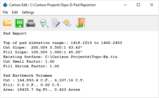
Cut outslope ratio <1.000>: 0.5 (a summary of the earthwork volumes will appear, your report will be slightly different):
Click the Exit (Doorway) icon to continue forward in the process:
Adjust parameters and redesign pad [Yes/<No>]? N
TIN Output: click Create New Surface
Merge Pad with Target Surface: click No
Output Triangulation to Write: use Topo-R.tin (R for Road)
Contour the pad [<Yes>/No]? N
Re-run the View -- 3D View -- Drawing Viewer command to view the drawing now with a road and click the Exit (Doorway) button when you're done reviewing the data.