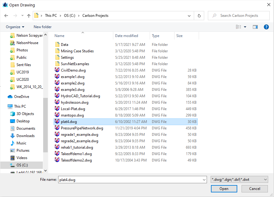
- If you get the Start Page, pick Open Files.
- If you get the Startup Wizard dialog box, click the Browse button.
- If you are taken directly into CAD, click File -- Open.
Verify the Survey module is loaded by clicking Settings -- Carlson Menus -- Survey Menu.
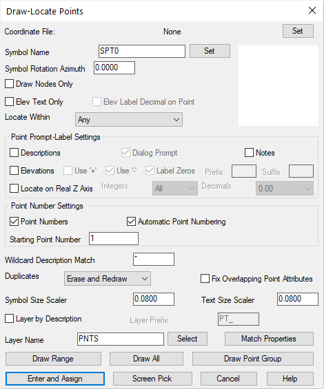
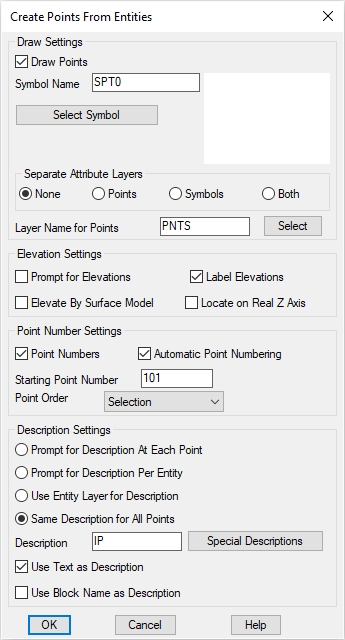
At the top, change the symbol to SPT0 by picking Select at the very top of the dialog, and choosing symbol SPT0 from the dialog of symbol choices (not shown here). Disable the prompting and labeling for Descriptions, Elevations and Locate on Real Z Axis (make them blank as shown). Match the other entries as shown (which are mostly the default conditions) and click Enter and Assign at the lower left and respond to the prompts as follows:
Enter North(y): 4809.17
East(x): 4391.28
The program will recognize that you have not yet started a coordinate file, so click the New tab and enter the File Name as Plat4.crd (which should be the default). If you enter Plat4, you do not need to enter the extension .crd. The program will add extensions automatically. You will see this:
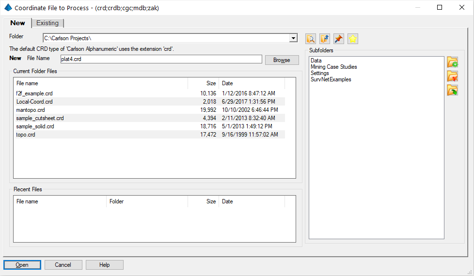
Click Open. You will be prompted again:
Enter North(y): press Enter
Traverse, Line OFF, RAW FILE OFF
Occupied Point ?
Pick point or point number: 1
Exit/Help/Options/Arc/Points/Line/SideShot/Inverse/Angle-Bearing Code <7>: 1
Enter Bearing Angle (dd.mmss) <90.0000>: 58.1848
Points/<Distance>: 736.73
Exit/Help/Options/Arc/Points/Line/SideShot/Inverse/Angle-Bearing Code <1>: e (to exit)
You could keep on traversing, but we will stop here to review. You have created point 2, traversing NE from point 1. To review, code:
- 1 is for NE
- 2 for SE
- 3 for SW
- 4 for NW
- 5 for Azimuth
- 6 for Angle Left
- 7 for Angle Right
- 8 for Deflection Left
- 9 for Deflection Right
Traverse, Line ON, RAW FILE OFF
Exit/Help/Options/Arc/Points/Line/SideShot/Inverse/Angle-Bearing Code <1>: 2
Enter Bearing Angle (dd.mmss) <90.0000>: 75.0627
Points/<Distance>: 553.69
Exit/Help/Options/Arc/Points/Line/SideShot/Inverse/Angle-Bearing Code <2>: e (to exit)
[Continue/Extend/Follow/Options/<Pick point or point numbers>]: 1-2
[Arc/Close/Distance/Extend/Follow/Line/Undo/<Pick point or point numbers>]: press Enter to end
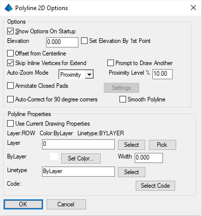
Now we have two vector entities. The first, from point 2 to point 3 is a Line. The second, from point 1 to point 2, is a Polyline (even though it is only one segment long). It will (by default) be a lightweight polyline (LWPOLYLINE). This can be verified by picking it using the Inquiry -- List. Polylines are linked combinations of one or more line/arc segments that behave as one unit. Carlson encourages the use of polylines versus lines because they offset as a unit, will take on a thickness or width, are easier to select and have superior editing capabilities.
NOTE: Many entities (e.g. lines, arcs, etc) can be turned into a polyline by issuing the Edit -- Polyline Utilities -- Entities to Polyline command but our next command will also offer this functionality.
To join the polyline and line entities into a single polyline, pick the Edit -- Join Nearest and set the prompts to those shown below and click OK when ready:
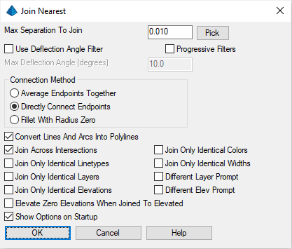
Select lines, arcs and unclosed polylines to join [Settings].
Select entities: pick the polyline from 1 to 2 and the line from 2 to 3, and then press Enter for no more
Now, see the grips on the new polyline by picking it with the cursor. See how the whole thing highlights? That is proof that it is joined up as a polyline.
Radius of Arc <0.000>: 500
[nea] Pick Point on 1st Tangent Line: pick on the 1st polyline segment closer to point 2
[nea] Pick Point on 2nd Tangent Line: pick on the 2nd polyline segment close to point 2
The arc draws in, and the centerline remains a polyline, now with 3 segments.
You can also inverse (go to) a snapped position on a line or polyline, such as the midpoint of an arc. Let's do that, because we want to traverse south from the midpoint of the arc. Key-in I and follow the prompts below:
Calculate Bearing & Distance from starting point?
Traverse/SideShot/Options/Arc/Pick point or point number: mid (for midpoint snap of)
Snap to MID of: select the arc
Traverse/SideShot/Options/Arc/Multiple/Pick point or point number: T
Traverse, Line ON, RAW FILE OFF
Exit/Help/Options/Arc/Points/Line/SideShot/Inverse/Angle-Bearing Code <2>: press Enter
Enter Bearing Angle (dd.mmss) <75.0627>: 10.11
Points/<Distance>: 400
Exit/Help/Options/Arc/Points/Line/SideShot/Inverse/Angle-Bearing Code <2>: press E to exit
Notice that you can transition from Inverse, to Traverse, to Sideshot, etc, with these COGO options. We were in inverse, but we did T for traverse, and could have done I for inverse to return to inverse. This cuts down on keystrokes, and adds to the sense of fluidity of the software.
Turn the resulting Line into a Polyline with the aforementioned Edit -- Polyline Utilities -- Entities to Polyline command as the following command requires Polyline entities.
Select all PRIMARY road polylines.
[FILter]/<Select entities>: press Enter (we will consider both these subdivision streets secondary)
Select all SECONDARY road polylines.
[FILter]/<Select entities>: pick the main centerline and pick the side road
[FILter]/<Select entities>: press Enter
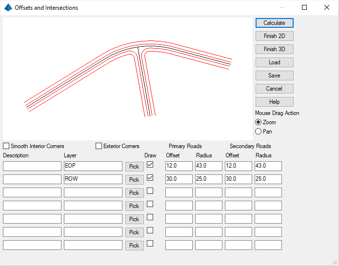
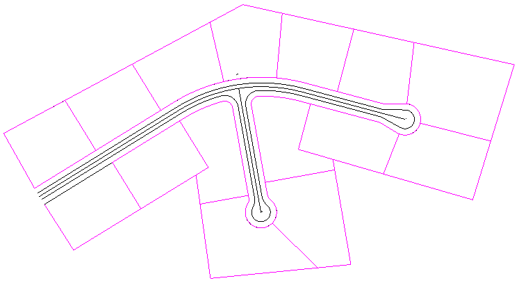
The street intersections are presented in a dynamic dialog as shown above. Try experimenting with different radii under the Secondary Roads column, then clicking Calculate. The streets will re-draw in the upper graphical area. But after experimenting, change the four values under Secondary Roads to those shown (ignore Primary Roads -- those don't apply here), and click Calculate. Then click Finish 2D. Note the drawn-out street intersection.
Now select the Inquiry -- Drawing Inspector command. Right click and make sure Layer is checked. Hover over the outside polyline (it is layer ROW). Hover over the next polyline inwards from the outer polyline (it is layer EOP). For example, if you had clicked off EOP under the Draw column in the above dialog, the edge-of-pavement polyline would not have drawn.
Select all offset polylines to end with cul-de-sac.
[FILter]/<Select entities>: form a crossing selection from right to left across the lower side road, selecting all 5 polylines (ROW-L, EOP-L, CL, EOP-R, ROW-R)
[FILter]/<Select entities>: press Enter
Pick cul-de-sac center projection onto centerline: pick near the endpoint of the centerline of the lower side road near point 4. Make sure the pick is on the centerline polyline, or the routine will say the centerline was not found.
This brings up the following dialog:
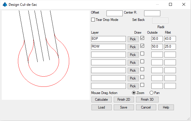
Again, you can change the Fillet Radius and the Outside Radius on the EOP or ROW, click Calculate, and check out its effect (don't make the Outside radii too small or it will fail to Calculate if there is no workable solution). Set values as shown above and then click on Finish 2D.
Select all offset polylines to end with cul-de-sac.
[FILter]/<Select entities>: form a crossing selection pick from right to left across the right main road, selecting all 5 polylines (ROW-L, EOP-L, CL, EOP-R, ROW-R)
[FILter]/<Select entities>: press Enter
Pick cul-de-sac center projection onto centerline: pick the endpoint of the centerline of the lower side road near point 3
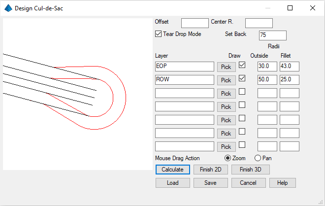
For a teardrop cul-de-sac, fill out the dialog as shown above then click on Calculate and Finish 2D.
NOTE: Teardrop cul-de-sacs allow moving vans and other large vehicles more turning room, and have been popular in many residential subdivision areas. Our drawing now appears as shown below, with the exception of the filled reference dots:
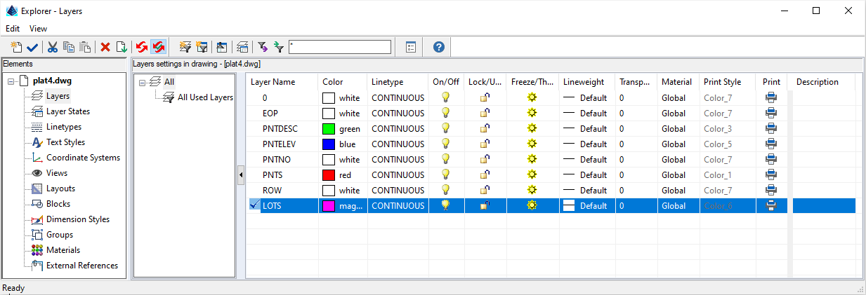
- Click on for New layer
- When Layer1 highlights, type over it with LOTS
- Click under the Color column and change the color to Magenta
- Click the (Set) Current button up top to make this layer current and then dismiss the dialog box
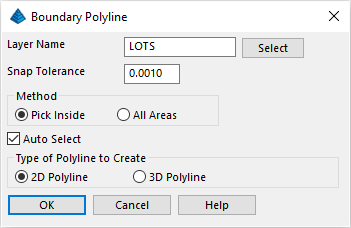
Our goal is to make 1-acre lots. The automated parcel creation tool prefers frontage lines that do not contain lots of zigs, zags, and jogs in the polylines as this may cause the perpendicular offset logic to fail to find a solution (Lot sidelines will radiate perpendicular from the frontage polyline). Not only should the front and back lines tend to run parallel with each other, but they should end at some point before the calculation runs into difficulty with impossible math.
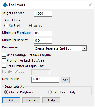
Fill out as shown. In particular, change the Remainder to Create Separate End Lot so that we force 1.000 acre lots and don't just get equal lots of some size such as 1.0017 (because the remainder lot that would not fit was added onto all lots). Using the Closed Polylines option means that our side lines will be doubled up, each lot sharing a side line. Click OK.
Select front polyline: pick north ROW
[Offset/<Select back polyline>]: Pick northernmost polyline (the back property line)
The 1.00 acres lots are laid out as far as possible. However, due to the geometry, it is likely that more Lots are able to be generated. As it turns out, the direction of the front polyline can have an impact on what is able to be created.
Select polyline or line to reverse: pick the ROW polyline and shows phantom direction lines of the new current direction (which are automatically removed when the command ends)
Re-run the Area/Layout -- Layout Utilities -- Lot Layout command. Use same dialog entries and when prompted:
Select front polyline: pick the ROW polyline in a convenient location
[Offset/<Select back polyline>]: pick the outer polyline at a convenient location
The result should look similar to that below, with the exception of the open reference dots:
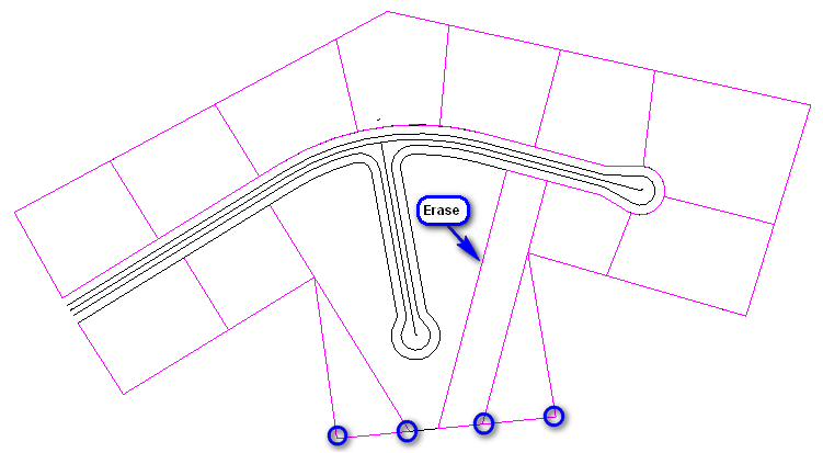
Let's clean this up for new work to follow:
- Click the Edit -- Erase -- Standard Erase command and erase the Lot as shown above.
- Let's remove polyline vertex locations which
permits to keep parts of the Lots intact. Click Edit -- Polyline
Utilities -- Remove Polyline --
Remove Polyline Vertex and when prompted:
Select polyline to remove from: pick one of the LOTS polyline (cue markers will display where vertex locations can be found)
Pick point to remove: pick one of the circled vertex locations shown above (the polyline changes shape)
Pick point to remove (Enter to end): pick the other indicated vertex location
Pick point to remove (Enter to end): press Enter
- Re-run the Remove Polyline Vertex command by pressing Enter and repeat the process for the other Lot indicated
When prompted:
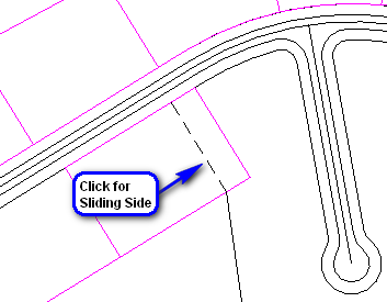
Define area by points or closed polyline [Points/<Linework>]? press Enter to accept the Linework option
Select polyline segment to adjust: pick the easterly-line of the Western lot as indicated by the dashed line
Keep existing polyline [Yes/<No>]? indicate the No response so the end result is a single lot polyline
Define new line by selected line, another line, angle or points [<Selected>/Line/Angle/Points]? press Enter to indicate the new lotline should be simply slid
(the current area is echoed for reference purposes)
Remainder/Yards/SF/<Enter target area (acres)>: type 1 to indicate the desired acreage size
Calculating ...
Done.
The new lot at the target size is drawn. Press the Enter key to repeat the command to adjust the westerly-line of the Eastern lot.
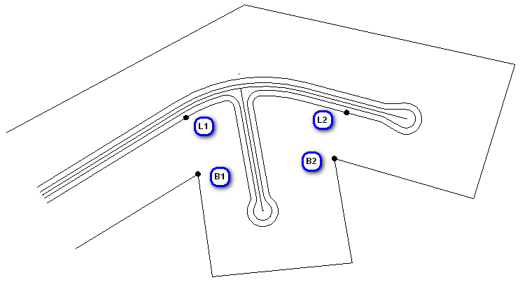
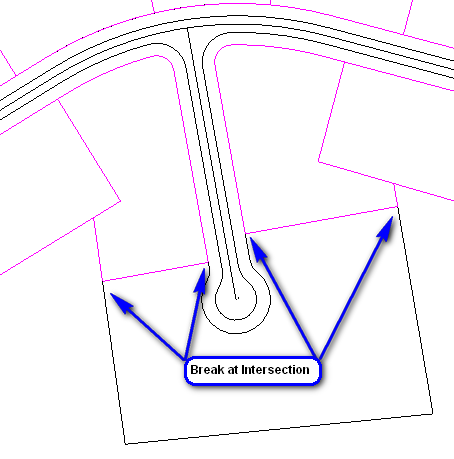
To do this, use the Edit -- Break -- At Intersection command and when prompted:
Select Line, Arc, or Polyline to Break: pick the lower back property line
[app on] Pick Intersection to break at: pick the B1 intersection point
Press the Enter button to repeat the command to break the lower back property line at B2.
[Continue/Extend/Follow/Options/<Pick point or point numbers>]: use a NEArest snap to start the polyline just south of B1
[Continue/Extend/Follow/Options/<Pick point or point numbers>]: use a PERpendicular snap to end the polyline at the ROW polyline
[Arc/Close/Distance/Extend/Follow/Line/Undo/<Pick point or point numbers>]: press Enter to end
Press Enter to re-run the command and repeat the process starting just south of B2.
Pick point inside area perimeter: pick inside either (or both) of the new lots (the results are echoed to the Command line area)
Pick area label centering point (Enter for none): press Enter to end
Pick point inside area perimeter: press Enter to end
The lot(s) is/are probably not the 1 acre target. We wish to obtain the target size but would prefer to work with a closed polyline perimeter for the new lots.
When prompted:
Pick an internal point: pick inside the new lot(s) (the new boundary polyline(s) are created).
Select Line, Arc, or Polyline to Break: pick the lower back property line
[app on] Pick Intersection to break at: pick a lower back property line break location cited in the image above
Press the Enter button to repeat the command to break the lower back property line at its other designated break point.
Press the Enter button in succession to repeat the command to break the right-of-way property line at its designated break points.
Fill out as shown, except change the Remainder to Apply Equally to All Lots so that we force a minimum of 1.000 acre lots and spread the remainder equally between the lots. Click OK and when prompted:
Select front polyline: pick the remaining ROW polyline
[Offset/<Select back polyline>]: pick the remaining lower back property line
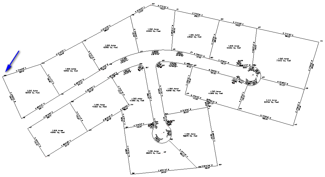
The lots are laid out as evenly as possible and our completed site should resemble the following:
It may not be the most aesthetic subdivision, but we learned a lot of tools making it. But we're not done. There's some real automation ahead.
Set the Starting Point Number to 101 (helpful as our previously entered points [1-4] can be thought of as "control" points) and verify the dialog as shown and click OK. A second dialog, covering what entities to capture, appears next:
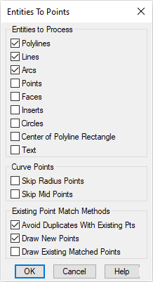
Accept the default settings and click OK. When prompted:
Select arcs, circles, faces, points, text, lines and polylines.
[FILter]/<Select entities>: type ALL and press Enter twice
All the point numbers for stakeout are created and stored into the active Coordinate File.
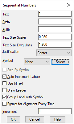
Click on the Select button to select a desired symbol to circumscribe our sequential numbers as illustrated below:
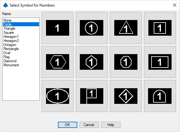
Choose the circled text and click OK to return to the Sequential Numbers dialog box:
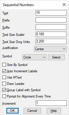
Set the Text value to 10 and the Text Size Scaler to 0.16 as shown and then click OK. When prompted:
Pick point for label position: pick near the center of the first upper left lot
Pick point for label alignment: press F8 for <Ortho on>, pick to the right
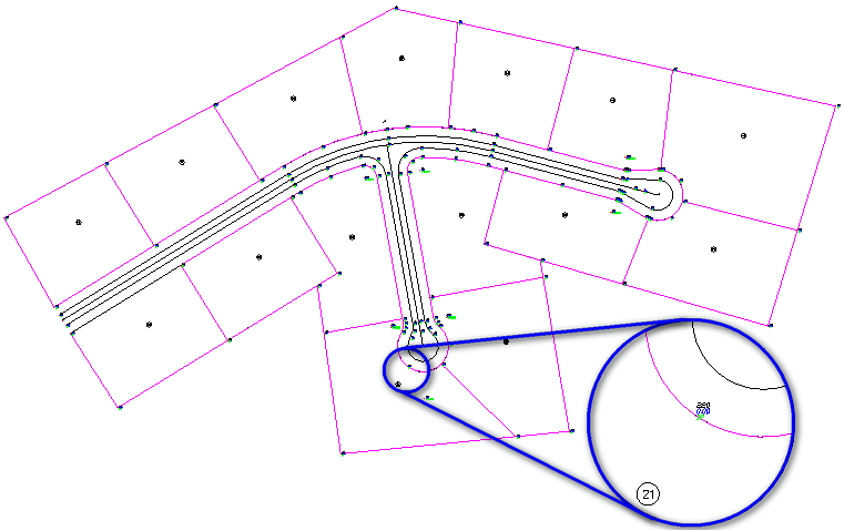
Now pick near the center of all of the lots, going clockwise and press Enter at the conclusion of the last lot. When complete, press F8 again to set Ortho off. The resulting drawing, with point numbers, is shown below (enhanced for clarity):
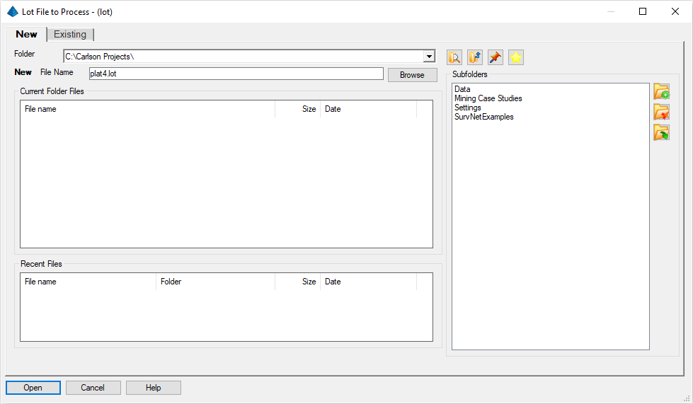
Next, issue the Area/Layout -- Create Lots -- Lot File by Interior Text. Supply the Lot File to Process value as shown below and click the Open button:
A dialog box will appear:
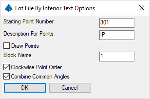
Set the values as shown above and click OK. When prompted:
Select lot lines, polylines and text.
[FILter]/<Select entities>: type ALL and press the Enter button twice
The Lot File will be created.
NOTE: If we had not made points at all lot corners using Create Points from Entities command, the Lot File by Interior Text would create points at the Lot corners. This is the reason for the Starting Point Number prompt. If points are found, no new ones are created. Lot files must have points at all the corners.
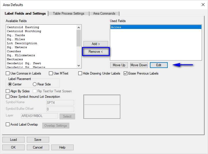
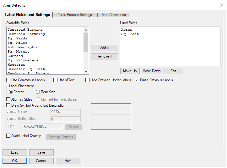
Use the Remove < button to remove the Sq. Feet entry leaving only the Acres item in the Items Used portion of the dialog box. Use the Edit button to verify it is set to plot to 3 decimal places (i.e. 0.000) and click OK to complete the command.
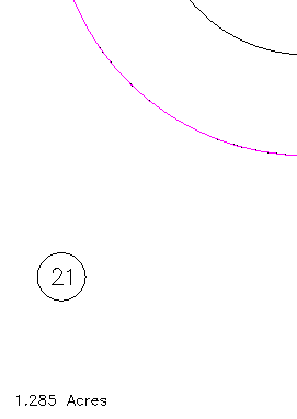
Now choose the Area/Layout -- Area by Interior Point command and when prompted:
Pick point inside area perimeter: pick inside Lot 10
Pick area label centering point (Enter for none): Pick near the center of Lot 10
Pick point inside area perimeter (Enter to end): repeat as prompted for Lots 11 through at least Lot 16 (continue with all Lots if you're so inclined) and press Enter when complete
A detailed illustration is shown below:
NOTE: For precise centroid placement, consider the use of the transparent Centroid snap ('centroid).
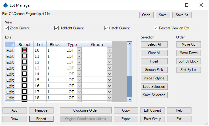
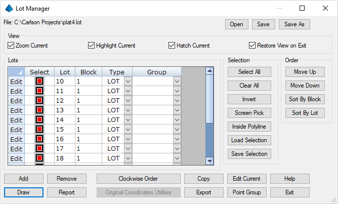
Pick on Lot 10 and click Report. This will lead to the Lot Report dialog box:
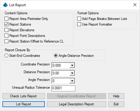
Be sure that your settings are as shown above and then click Lot Report:
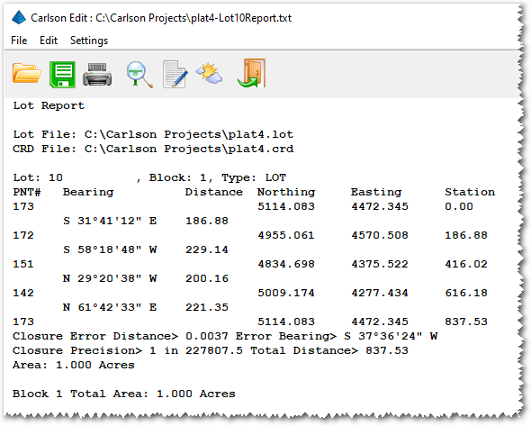
This dialog is typical of the many Carlson Standard Report Viewer dialogs. You can click on one or more lines, highlight them and hit the delete key on the keyboard, and these lines will delete. You can edit lines directly in the dialog. You can also save the report to disk with the Save icon shown above. To exit, click the Exit (Doorway) button. The Lot Manager dialog box returns.
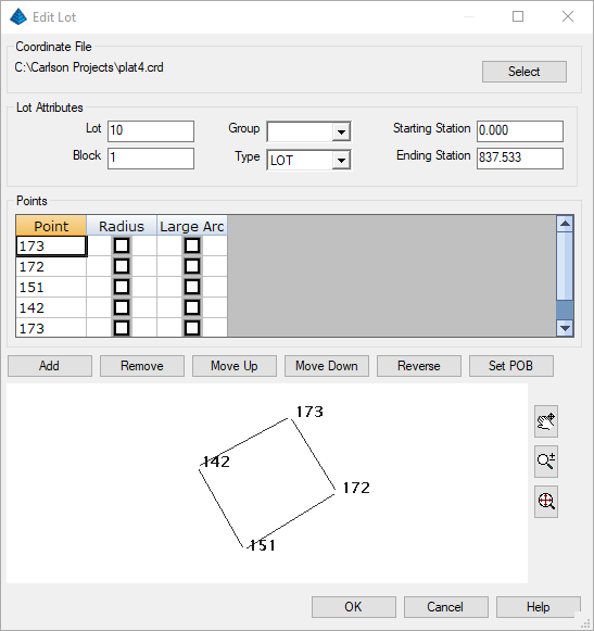
With Lot 10 selected, click Edit Current to display the dialog box above. Note the graphic display in the lower half, which maps the Points associated with the Lot. Also note the Northwest corner point number for Lot 10 as we'll use this information in the next step. Click Cancel and then Exit on the Lot Manager dialog box.
Remember the Northwest corner point number for Lot 10? Let's change its coordinate value. Issue the Points -- Edit Points command. A spreadsheet appears. Scroll down to your point number (142 in the image cited above):
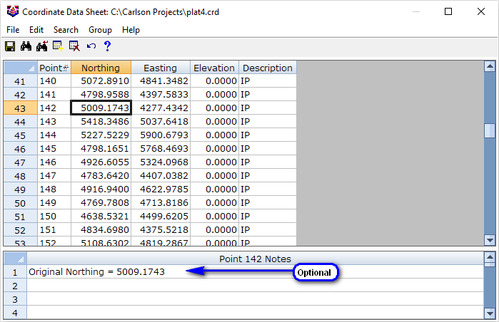
Click on the Northing and edit it to 5050. This is for illustration purposes. In reality, you might be fine-tuning your subdivision design points. As long as the same points define the lots, you are, in effect, able to make a ready-made new drawing. Once complete, issue (from the Coordinate Data Sheet dialog box) the File -- Save and Exit option.
Then choose File -- New and exit the Startup Wizard (if it appears), and go straight to the Area/Layout -- Lot File Manager command is it also provides the tools for drawing Lot Files into the drawing:
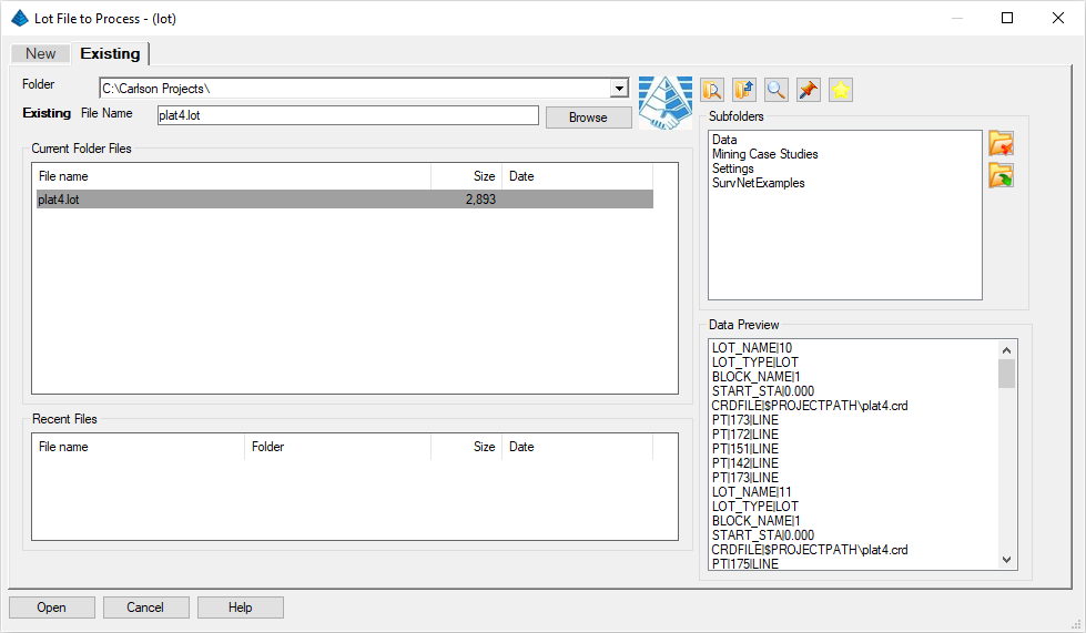
From the Existing, select the *.lot file specified above and click Open. Follow this and select the existing Plat4.crd file from the earlier project. When the Lot Manager dialog appears, choose all Lots by clicking Select All and then click Draw.
We have the ability to further define how the Lots are drawn and/or labeled:
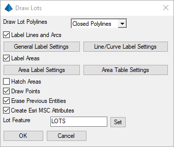
Apply settings required or as shown in the image above and:
- Click the Line/Curve Label Settings button to
display the Auto-Annotate
dialog box (also found under the Annotate menu)
and set the values as shown below:
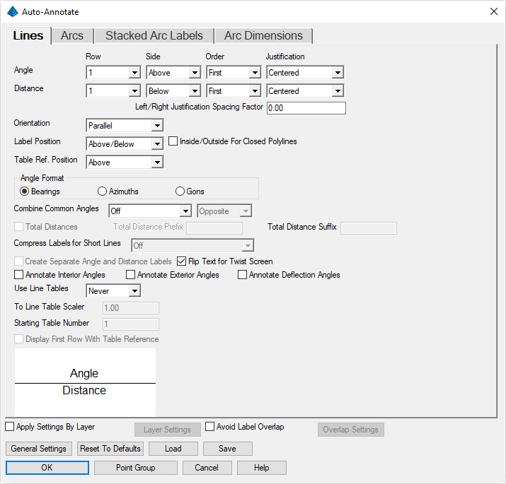
Click its OK button when complete. - Click the Area Label Settings button to
re-confirm the display the Area Defaults options
discussed earlier (also found under the
Area/Layout menu). Let's reuse the Sq.
Feet item to the Used Items as shown
below:
Click its OK button when complete.
This leads to the plot shown below (drawn at 1" = 60' for clarity), created entirely from stored Lot Files, and showing our revision of Lot 10: