- If you get the Start Page, pick New Drawing.
- If you get the Startup Wizard dialog box, click New.
- If you are taken directly into CAD, click the File --
New command.
NOTE: If you want to consistently use the Startup Wizard, issue the Settings -- Carlson Configure -- General Settings and enable the Use Startup Wizard option. Click OK to dismiss the dialog boxes. The Startup Wizard will be used the next time the software is started.
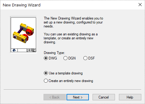
- Choose the DWG document type and the desire to base the
document on a Drawing Template as illustrated
below and then click Next >:
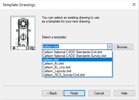
- Choose the carlson.dwt as illustrated below
(or site.dwt if carlson.dwt is not available) and click
Finish:
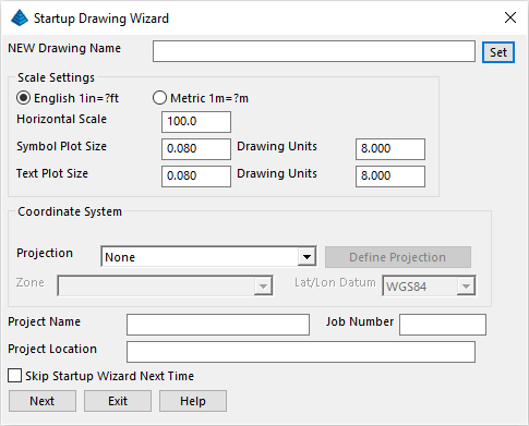
- We can now begin the more pertinent settings for the project to
come based on some preliminary settings that should be similar to
the default scenario shown below:
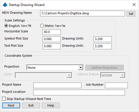
- Click Set at the top of the dialog box, and
enter in a NEW Drawing Name called Digitize.
Verify that the other settings match the settings shown below, and
click Next:
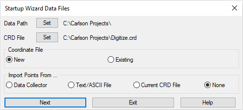
- You will see the Startup Wizard Data Files dialog to
set/confirm where to store data and indicate an information source
for points/coordinates. Set/match the values as shown below and
click Next:
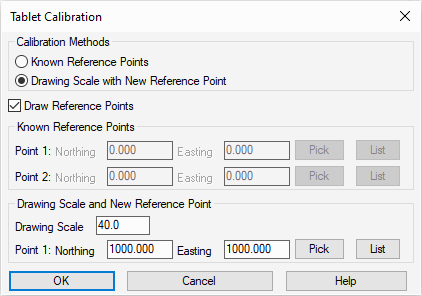
There are two different Calibration methods:
- Known Reference Points: allows you to enter in the coordinates of two marked points on the paper plan. This method applies when you know the coordinates of at least two points on the paper plans.
- Drawing Scale with New Reference Points: allows you to set up a coordinate system for the plans by entering the plan scale and picking any two points from the paper plan with the digitizer puck.

When prompted:
Digitize the First Reference Point: digitize on the target icon in the lower left
Digitize the Second Reference Point: digitize on the target icon in the upper right
The first point is assigned the coordinate specified earlier in the Calibrate dialog box and the second point is assigned coordinates to match with the plan scale. From now on, all of your points will be in relation to these two points.
NOTE: Generally, you want to pick points on the drawing that you can find and use again in case you need to recalibrate. Also, the further away the points are from each other, the more accurate the coordinate system will be.
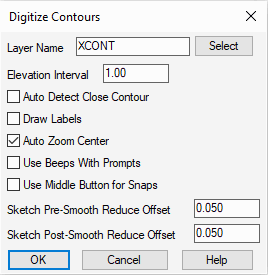
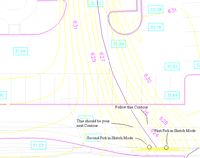
Set the values as shown above (making note of your applicable contour interval) and click OK when ready. The rest of the prompting occurs at the command line and starts with the contour elevation. Find the lowest elevation for the Existing contours labeled in the bottom right corner of the paper plan zoomed in on below. In this example, the lowest elevation is 624 feet. You want to enter in the lowest contour so that as Carlson CADnet adds the Elevation Interval, it is from lowest to highest. The elevation can be entered either with the digitizer puck keys or with the computer keyboard. The layout of the digitizer keys is set in Digitize -- Digitizer Settings -- Puck Layout.
When prompted:
Increment(1.00)[A]/Direction(+)[B]/Elevation <0.00>: indicate 624 and press Enter
Sketch[0]/Exit[A]/Pick the first point: type in [0] and press Enter to get into Sketch Mode. In Sketch Mode, you will be prompted to "Pick and drag." The first point you pick is the starting point of a contour. Drag is asking you to follow that contour with the digitizer puck on the paper plan. Click a second time when you have traced the entire contour and have reached the end of the contour. You will then be prompted as follows:
Pick[0]/Close[A]/Undo[B]/Pick and drag (Enter to end): indicate [A] to close the contour. Indicate [B] for Undo if you made a mistake and need to sketch part of the contour again. [0] will switch you into Pick Mode.
Increment(1.00)[A]/Direction(+)[B]/Elevation <625.00>: press Enter to accept the next elevation in the series and continue to digitize the next contour elevation. However, pick [0] to get into Pick Mode. In Pick Mode, you do not have to trace the contour. Rather, pick with the digitizer puck to create points that will make up the contour. When all contours are digitized, press E to exit the routine.
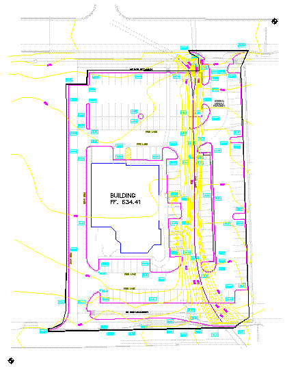
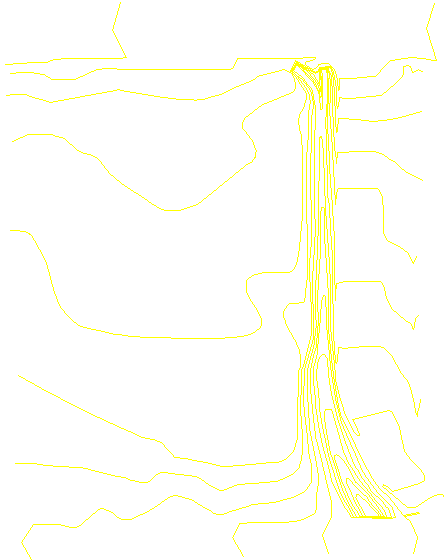
NOTE: When in Pick Mode, less picks are needed on fairly straight segments. Conversely, more picks will give you a more accurate contour. When completed, the Existing contour map should resemble the following:
Let's begin by digitizing the main building. Issue the Digitize -- 2D Polyline command (2D Polyline is used to digitize line work entities with one elevation) to display the dialog box below:
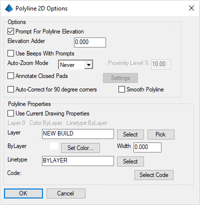
Set the values as shown above and click OK when ready. When prompted:
Enter polyline elevation <0.00>: 634.41 and press Enter (this is the value annotated in the middle of the building)
First point: pick a building point
Arc[0]/Close[A]/Undo[B]/Osnap[.]/Pick next point (Enter to end): pick the next building point
Arc[0]/Close[A]/Undo[B]/Osnap[.]/Pick next point (Enter to end): repeat...
Arc[0]/Close[A]/Undo[B]/Osnap[.]/Pick next point (Enter to end): pick the last building point
Arc[0]/Close[A]/Undo[B]/Osnap[.]/Pick next point (Enter to end): A to close
Digitize Another NEW BUILD Polyline [Yes(A)/<No(B)>]? B for No
Notice that the parking lot line work consists of different elevation levels. For this scenario, we'll use the Digitize -- 3D Polyline command which displays a dialog box similar to that shown below:
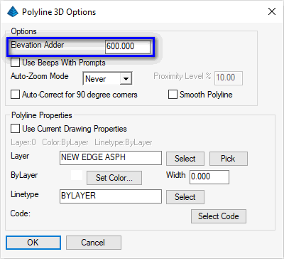
NOTE: Because the parking lot elevation labels have been shortened on the paper plan (e.g. they read 35.37 and 35.12), be sure to set the desired Elevation Adder. Set the remaining values as shown and click OK when ready. Let's start by digitizing the parking lot starting from the zoomed in section below:
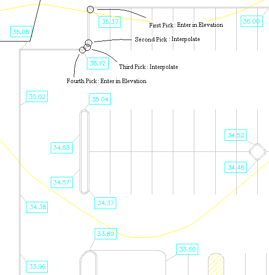
The edge of asphalt is the inside line. When prompted:
First point: Click on the point with the digitizer puck where the 35.37 elevation label points to in the upper left corner of the parking lot
Elevation[B]/Object/Osnap[.]/Next point or elevation<Interpolate>: 35.37 and press Enter
Arc[0]/Close[A]/Undo[B]/Osnap[.]/Pick next point (Enter to end): pick below the first point where the line work starts to curve. We do not have an elevation for this point, but we can interpolate the elevation from the two points around it using the Interpolate option.
Percent/Ratio/Interpolate[A]/Degree/Object/<Elevation[B]> <635.37>: A
This point elevation will be interpolated upon completion.
Arc[0]/Close[A]/Undo[B]/Osnap[.]/Pick next point (Enter to end): A
Percent/Ratio/Elevation[B]/Degree/Object/Osnap[.]/Next point or elevation<Interpolate>: pick the middle point of the curve
This point elevation will be interpolated upon completion.
Percent/Ratio/Elevation[B]/Degree/Object/Osnap[.]/Next point or elevation<Interpolate>: pick the end of the curve at the 35.12
Percent/Ratio/Interpolate[A]/Degree/Object/<Elevation[B]> <635.37>: 35.12 and press Enter
Continue digitizing for the rest of the edge of asphalt linework. Digitize each point where there is an elevation label and each point where the curb line changes direction and press Enter when complete.
Digitize Another NEW EDGE ASPH Polyline [<Yes(A)>/No(B)]? indicate No
To check the elevations of the interpolated points, issue the Inquiry -- Drawing Inspector command and hover over the polyline you just created. A window will appear showing you information about the polyline. If no elevations appear, right+click and enable the Display Elevations option.
Use the 3D Polyline command to digitize the rest of the parking lot as seen below.
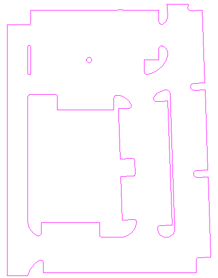
To approximate the area of the main building, pick the points of the building outline.
Pick starting point: Pick points as close to the building design line work as you can
Undo[B]/Pick next point (Enter to end): repeat... (press Enter when done)
Digitize Another Area [<Yes(A)>/No(B)]? B
An Area Report similar to the one shown below appears:
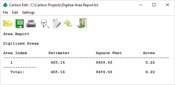
Click the Exit (doorway) icon.
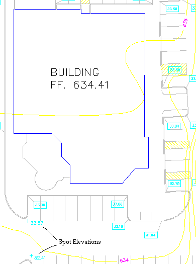
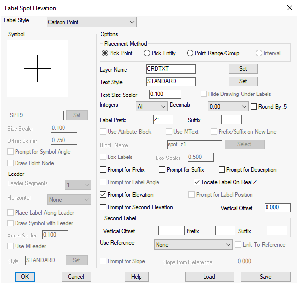
To digitize these elevations, we can use the Digitize -- Spot Elevation command. Fill out the dialog as shown and pick OK when ready:
When prompted:
Point to Label?
Pick point or point number: find and click on the spot elevation labeled 632.57
Elevation <0.00>: 632.57
Point to Label (ENTER to End)?
Pick point or point number: find and click on the spot elevation labeled 632.41
Elevation <0.00>: 632.41
Point to Label (ENTER to End)?
Pick point or point number: press Enter
When prompted:
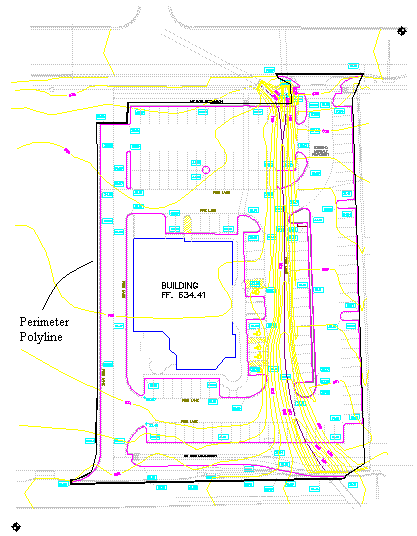
Layer name <PERIM>: PERIMETER and press Enter
First point: pick the first point on the boundary
Arc[0]/Close[A]/Undo[B]/Osnap[.]/Pick next point (Enter to end): pick the next point on the boundary
Arc[0]/Close[A]/Undo[B]/Osnap[.]/Pick next point (Enter to end): repeat...
Arc[0]/Close[A]/Undo[B]/Osnap[.]/Pick next point (Enter to end): C
Digitize Another PERIMETER Polyline [<Yes(A)>/No(B)]? indicate No
Select boundary polylines.
[FILter]/<Select entities>: pick the perimeter polyline created in the previous step
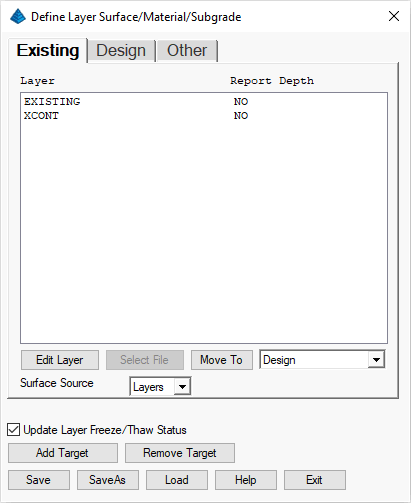
- Existing - Used to model initial/pre-construction site conditions.
- Design - Used to model proposed/post-construction site conditions.
- Other - Used as a collection of unknown/irrelevant site conditions (text notes, hatches, etc).
| Existing | Design | Other |
|---|---|---|
|
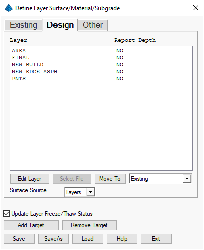
|
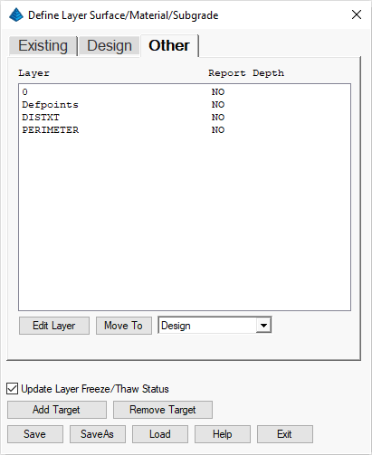
|
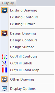
Now that the layer targets are defined, there are several commands that can be applied. In the Display menu (SiteNET in Civil), you can turn on/off whether to display layer targets by using the Existing Drawing, Design Drawing and Other Drawing commands:
Practice turning on/off the Existing Drawing, Design Drawing and Other Drawing through the Display menu:
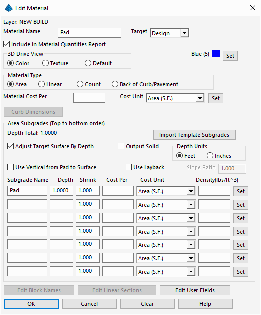
Next pick layer NEW EDGE ASPH and click the Edit Layer button. A dialog appears for defining what will be the Pavement material properties. Set the values as shown below and click OK when ready:
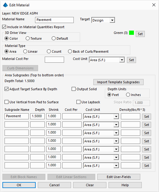
After the modifications have been made, pick Save and Exit.
Now let's visually verify the subgrade areas. Issue the Takeoff (or SiteNET) -- Subgrade Areas -- Hatch Subgrade Areas to display the dialog box below:
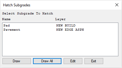
Select a desired subgrade layer and click the Edit and establish the following settings:
| Subgrade | Hatch Pattern | Color |
|---|---|---|
| Pad | Hex | Blue |
| Pavement | Asphalt | Green |
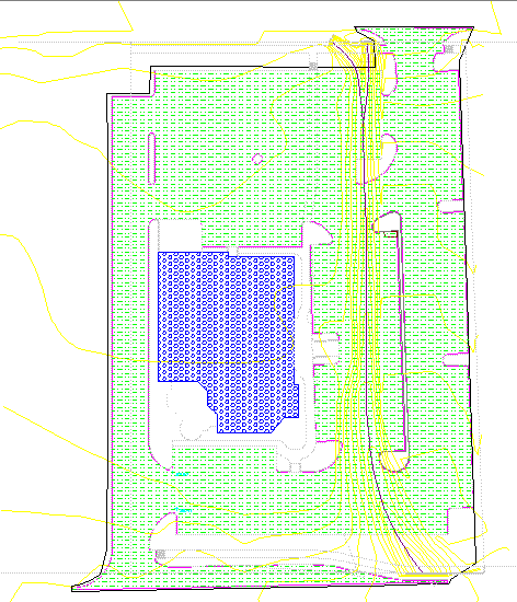
The resulting hatch areas show where the subgrade is applied. Notice how the islands are not hatched because they are curb polylines that are already inside another curb polyline. Takeoff -- Subgrade Areas -- Erase Subgrade Hatches command.
- existing ground, and,
- design considerations
- To make the Existing Ground surface, issue the Takeoff -- Make Existing Ground Surface. The program will process the entities (regardless of their screen visibility) and make the triangulation surface.
- To make the Design Ground surface, issue the Takeoff -- Make Design Surface.
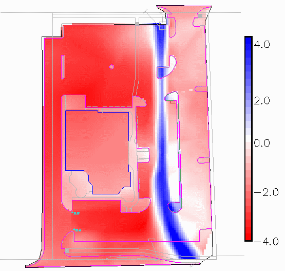
Let's remove the shaded hatch of the Cut/Fill color map through the use of the Display -- Cut/Fill Color Map command.
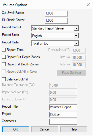
Set the as shown above and click OK when ready to display a volume report similar to that shown below:
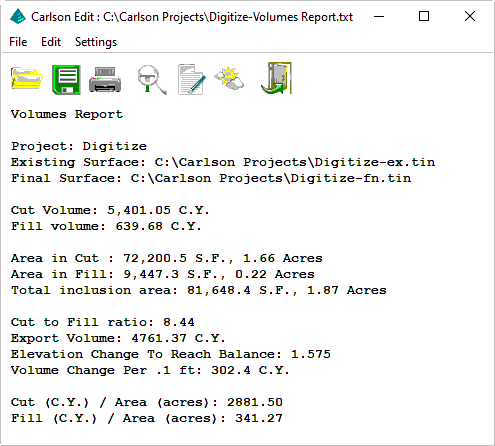
Click the Exit (doorway) button to exit the report viewer.
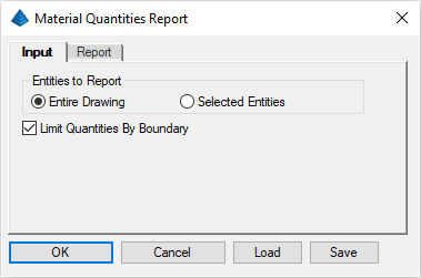
Specify the options as shown above (feel free to explore the options in the Report tab) and click OK when ready. The report includes (among other this) the:
- Count, and,
- Length, and,
- Area, and,
- Volume
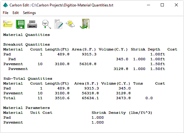
Click the Exit (doorway) icon when ready. The Takeoff -- Material Quantities -- Custom Report command can be used to report these values with control of the report format and the option to export to Excel.