This command allows you to set up the default settings that are used each time you start a new drawing, or load an existing drawing.

NOTE: When using Carlson products with an "embedded AutoCAD OEM engine" (e.g. Carlson Survey with Embedded AutoCAD or Carlson Takeoff with Embedded AutoCAD), only a subset of the various configuration commands will be available.
Load: This command permits a previously saved configuration (CFG) file to be loaded into the software and is useful for propagating corporate standards to groups or individuals within an organization.
SaveAs: This command "packages" up all current configuration settings and permits them to be saved to a named configuration (CFG) file that can be shared with users of Carlson Software.

Use Startup Wizard: When enabled, a dialog-based "wizard" interface is used for the creation of a new project
Generate Report Log: When enabled, output from several commands will be accumulated in a report buffer. Commands that output to the report log include Inverse, Traverse, Curve Info, etc. Also, any report that is displayed in the standard report viewer is also added to the report log. While activated, the report log resides in the lower left corner of the desktop as a minimized title bar that shows how many lines are in the report buffer. To view the report log, pick on the maximize icon on this title bar. You can also view the report log by running the Display Report Log function in the Inquiry menu. The report log can be edited, saved to a file or printed. To quickly turn the report log on and off, you can type REPORT at the command prompt.
Save Drawing INI Files: This option stores the file names of data files used with
the current drawing. When enabled, an .INI with the same name as
the DWG file will be created to store the data file names. These
file names are used for the list of recent files when selecting
data files and the Drawing Explorer
command manages the list of these data files.
Save Settings To Drawing Dictionary:
This option saves the settings for commands within the drawing.
Commands always store settings at the program level for recall the
next time the commands are run. By storing settings with the
drawing, each drawing will recall the command settings used in the
drawing. For example, if you run Triangulate & Contour at an
interval of 5 in Drawing_A, then use interval 1 in Drawing_B, then
the next time you contour in Drawing_A it will recall interval 5
instead of using the last interval of 1.
Ignore Zero Elevs: This option will ignore any entities with a zero elevation. It is used for many commands, such as Triangulate and Contour or Make Grid File.
Use South Azimuth: Turning on this option will use a South Azimuth instead of a North Azimuth as the basis for 0°.
Use Dview Twist Angle: This will use the screen Twist Angle defined with the command DVIEW. This is similar to Twist Screen.
Set DIMSCALE to Drawing Scale: This will set the dimension scale to match the drawing scale.
Set AUNITS to Drawing Angle Mode: This will set the DWG angular units to match the angle mode established under Drawing Setup.
Set PDSIZE to Symbol Size: This will set the PDSIZE scale to match the symbol size defined in Drawing Setup.
Set INSUNITS to Unitless: This will set the INSUNITS (Insertion Units) CAD system variable to Unitless (INSUNITS=0) when the drawing is opened.
Set MENUBAR on Startup: When enabled, the Carlson Menu associated with the Carlson icon (usually on the PC Desktop) will be loaded. Otherwise, use the Carlson Menus command to select the desired menu.
Set UCS to World on Startup: When enabled, drawings with a User Coordinate System (UCS) other than World will have the UCS set to World.
Set LTSCALE on Startup to Drawing Setup: When enabled, the linetype scale (LTSCALE) variable will be set to the Horizontal Scale defined under Drawing Setup.
Use Software Rendering: When enabled, commands that use OpenGL functionality (such as 3D Viewer Window) on computers with older video cards that don't offer extensive hardware acceleration will attempt to render the information with any available random-access memory (RAM).
Use Dialog For Selection Set Filter: For IntelliCAD, this option chooses whether to prompt for selection set filters in a dialog or command prompt at the "Select objects" prompt.Use Annotative Text: When enabled, text (usually placed through the Annotate Menu commands) will use scale-able annotative properties.
Support All Drawing Scales: When enabled, text placed as annotative entities will make use of all annotation scales currently defined within the drawing.
Set Annotative to Drawing Scale: This option sets the annotative scale to match the Horizontal Scale set in the Drawing Setup command.
Annotative Scale Prefix/Suffix:
These strings are used for naming annotative scales when the
program creates new annotative scales. For example, when the
program creates an annotative scale for a horizontal scale of 50,
you can name the annotative scale as 1:50 or 1"=50' depending on
these string settings.
Coordinate Report Order: You can choose the traditional North-East format, or reverse these in reports with an East-North format.
Date Format: You can control the display of dates in Carlson reports with this drop-down menu. The default is "Windows Setting" which allows you to control it with Windows Control Panel. Several other common formats are available.
Formatted Document Type: (AutoCAD-based platforms, only) Use this option (for commands such as 3D Viewer Window to establish the type of document produced by the command.
Report Viewer: This option chooses between the Carlson Report Viewer, Windows Notepad and Microsoft Word for the viewer to use for reports that the Carlson commands generate.
AutoCAD Menu: (AutoCAD-based platforms, only) This option chooses which AutoCAD menu to load when picking the AutoCAD menu from the Carlson Menus toolbar or from the Settings → Carlson Menus pull-down menu. When AutoCAD Map is installed, there are different layouts of the Map menu to choose from. When Autodesk LandDesktop is installed, those menus are available.
Object Linking: The Object Linking section contains options for creating additional "intelligence" on Carlson-placed entities:
Database Format: The Database Format chooses between Microsoft® Access 97 or 2000 (and higher) format. This database format applies to creating new database (.MDB) files in the GIS module, the drillhole database and the Export to Microsoft® Access option in the Report Formatter.
Coordinate File Format: Carlson can be configured to utilize a variety of coordinate file formats:
Remove Arcs: Since 3D polylines do not allow true arcs, the program represents arcs in 3D polylines as a series of short chords. The Remove Arcs settings control the spacing of these arcs:

Digitizer Puck Layout & View: There are two main formats for the digitizer puck. They are numbered 1 and 2. Selecting the View button brings up the window showing the two formats.

Use Mouse: This option allows you to use the mouse instead of the digitizer puck for the digitize commands.
Auto Tablet On for Digitize Commands: This option will activate the tablet when using the digitize commands.
Auto Tablet Off for Digitize Commands: This option will de-activate the tablet when using the digitize commands.
Several settings under Drawing Setup are used to establish the default values provided in the Startup Wizard and are identical to those discussed in Drawing Setup. There are a few additions, such as Vertical Scale, Point Prompt-Label Settings, Point Number Settings and Vertical Angle Mode.

There is also the ability to maintain two different sets of defaults (English and Metric). The user can maintain a comfortable set of settings for either unit system, especially if they constantly switch back and forth. Also added was support for meters/metres, tons/tonnes and various date representation which can be accessed via the Localization Settings button.
Please refer to the Set Project/Data Folder command for complete information.
These options are used for starting Carlson. Defaults are set here, and will be used at the beginning of each session.

Template Name: This is the drawing template file that will be used when starting a new drawing. The Browse button allows for selecting a new file.
Carlson Launch Folder: This is the folder where Carlson projects would be stored by default. The Browse button allows for selecting a new folder location.
Profile Name: This is the AutoCAD/IntelliCAD Profile that will be used when working in Carlson. If you use a custom profile, be sure that the profile contains the Carlson support folder in the Support File Search path (ie. %appdata%\Carlson Software\Carlson version\CAD version\SUP), and the Carlson main menu must be loaded. If the custom profile doesn't have these requirements, then the program switches to the default Carlson profile.
AutoCAD command switches: This turns off the AutoCAD "splash" screen upon launching the program. The /nologo takes the splash screen out of the start-up procedure. See AutoCAD documentation for other switches that are available for use.
AutoCAD product to run: (AutoCAD Only) This is the AutoCAD version and flavor (Map or LDT, etc.) that Carlson is installed for, and will run with.
No menu resetting: (AutoCAD Only) This controls whether to set the Carlson menu as the main customization file on startup or to keep the current main customization unchanged.

CG Survey Menu: Indicate whether to add-on the C&G Survey pull-down menus to the standard Carlson Survey menus. The Compact mode has all the C&G commands in a single pull-down menu. The Expanded mode has all eight C&G pull-down menus that C&G "stand-alone" used to have.
Initial Traverse/Sideshot Angle Mode: This sets the default angle mode for these COGO commands.
Show Occupy and Backsight Points on Status Bar: This is an option for the COGO Inverse command.
Automatic Raw File On: This is equivalent to toggling on the COGO → Raw File On/Off automatically when the drawing is opened.
Automatic Line On: This is equivalent to toggling on the COGO → Line On/Off automatically when the drawing is opened.
Automatic Point Object Snap On:
This is equivalent to toggling on the Settings
→ Point Object
Snap On/Off automatically when the drawing is
opened.
Automatic Compare DWG points with
Coordinate File on Startup: This option
runs the Coordinate File Utilities > Compare Points routine when
the DWG file is opened to report any differences between the point
entities in the drawing and point coordinates in the coordinate
file.
 Most of
the Surface/Triangulate & Contour commands will remember the
settings and parameters used from drawing to drawing. There are
some in this screen that will be used for gridding and modeling.
Most of
the Surface/Triangulate & Contour commands will remember the
settings and parameters used from drawing to drawing. There are
some in this screen that will be used for gridding and modeling.
Inverse Distance/LeastSquares Modeling Parameters: The modeling methods of Inverse Distance and Least Squares are similar ways to create a grid from datapoints or drillholes. It is not recommended to use these methods for gridding contour or breaklines. Triangulation is better for that. These methods need a search radius defined. Anything past this distance from one data point to the next will be ignored for influence. The Max Samples are the number of data points that will be used to influence each data point. The area is broken into 4 quadrants. The Min and Max Quadrant are the numbers of data points that will be used in each quadrant.
Specify Grid Resolution As: There are two ways to create a grid file. Once the boundary has been selected, the cells need to be determined. Number of Cells in X and Y will divide the boundary up into the specified number of cells. These will then be odd shaped rectangles, with the size calculated by the boundary dimensions and the number of cells. The Dimensions of Cells is the more commonly used method. This will allow for a set cell size for the X and Y directions. Most of the time the grid cells should be square, where you set the size.
Grid Precision: This is the number of decimals that are stored in the grid file.
Draw Contours Max Number of Rechecks for
Crossings: Routines that generate
contours check for any crossings that can occur from smoothing or
reduction options. When a crossing is found, the smoothing or
reduction factors are reduced and then the contours are rechecked
in case that adjustment causes a new crossing. This option can be
used to decrease the number of rechecks in case your dataset is
large and you don't want to take the time for these
checks.
Save Grids Using Binary Format: This
options chooses between saving .grd files as either text or binary
files. This setting applies to all routines that save grid files.
The advantage of the text format is the ability to view the grids
using any text editor like Notepad and the ability for non-Carlson
programs to easily read the grids. The advantage of the binary
format is the speed of saving and loading the grids which is
several times faster than the text format. Only Carlson 2015 and
later versions can read the binary format. When the range of
min/max grid values is small enough relative to the grid precision, the
program will automatically switch to an indexed binary format which
uses half the file size and loads twice as fast.
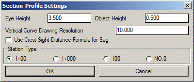
This configuration box is used mainly for text and drafting settings. Items such as text size scalers and station types are set here and will apply to the current and/or future drawings. These are very self-explanatory and are up to the user to set if something other than the defaults is desired.
Stage-Storage File Format: Indicate the format of the Stage-Storage File to be used in Carlson Hydrology.

These options are settings for prompting when entering the Mine notes. They are simply turned on or off for customized mine note entry. The Spad and Offset symbol sizes are set here for drawing in CAD. The layers for pillars and the Perim for underground mine design are set here. They can be customized so the program will recognize specific layers for commands such as volumes by grid or average, and calculating the extraction ratios.

This is the configuration screen for default settings used with the Mining Modules. Each item is detailed below.

Inverse Distance/Least Squares/Triangulation Search Radius, Samples and Quadrants: The modeling methods of Inverse Distance and Least Squares are similar ways to create a grid from datapoints or drillholes in that they use the same settings. It is not recommended to use these methods for gridding contour or breaklines. Triangulation is better for that. These methods need a search radius defined, while triangulation just uses the search distance to find the next data point to triangulate to. Anything past this distance from one data point to the next will be ignored for influence. The Max Samples are the number of data points that will be used to influence each data point. The area is broken into 4 quadrants. The Min and Max Quadrant are the numbers of data points that will be used in each quadrant.
Fill in Missing Strata Above/Below Existing
Strata (Seam Stacking/Conformance): This important setting is used for gridding and modeling
from drillholes. It does two things. The first item it controls is
to fill in missing strata. For example, if a drillhole does not go
deep enough to penetrate a deep seam, or a drillhole is drilled
down in a valley or low spot, it will either fill in (carry the
seam through the hole) or pinch it out at the hole. NONE will not
fill it in, meaning it will pinch the seam out at the shallow or
partial hole. ALL will not pinch the seams out at the shallow or
partial hole. Seam-Specific will use the Define Strata settings
where the marker and target beds are defined. The second modeling
concept this controls is conformance. In these same partial holes
where certain seams are not encountered, when it fills them in, it
controls how it behaves. NONE will let each seam do want they want,
independent of any other seam. ALL has all the seams looking at
each other and they all conform to each other. Seam-Specific will
use the Define Strata settings where the marker and target beds are
defined there. The marker bed is the "main" seam and other seams
will conform to it. There can be more than one marker seam. There
is also a hierarchy for conformance, so if the main marker seam is
not present, then the next marker seam in line will
prevail.
Use Conformance for Channel Samples: This option controls whether to use channel samples as source data points for conformance of other strata.
Calculate Strata Pinchout and slide bar: This setting determines if the thickness of a seam is pinched out when it does not occur in a drillhole. Turn it on to activate pinchout. If a seam is not present, it will pinch it out using that drillhole. If it is off, it will carry the seam through the hole where the seam is not encountered. The slide bar determines the distance between the drillholes for pinchout. Near zero will pinch the seam closer to the hole where it does not appear. Non-zero will pinch the seam closer to the drillhole where it does appear. Most of the time, the best estimate is to leave it in the middle, where it will pinch the seam halfway between the holes. It is also recommended to have the pinchout turned on when making thickness grids. This will model the thickness properly. But, when modeling the bottom elevation of a seam, turn OFF pinchout. If it is on, many times it will bring the elevation of the seam up to the next seam to pinch it out. Turning the off for elevation grids will keep them down where they belong. Then just add the thickness and the bottom elevation to obtain the roof elevation grid.
Pinchout Zero Thickness: This setting will recognize a zero thickness entry in a drillhole and treat it as a pinchout for modeling. Normally, the zero entry is treated as a zero value, and the seam would go to zero just at the hole, and not before. Treating a zero value in a drillhole as a pinchout, will treat it as if it wasn't in the drillhole, and the seam will be pinched out using the pinchout slide bar settings above, instead of just going to zero right at the hole.
Pinchout Key Only: This setting will apply the pinchout settings to just the
Key seams in the drillholes. The NonKey seams will model as if the
pinchout setting is off.
Adjust Non-Key for Estimated Key
Strata: This setting controls whether to adjust non-key strata
to fit in key strata for pinchout or conformance.
Restrict Pinchout to Drillhole Elevation Range: This setting provides the option to control where the seam will pinchout. If there is a shallow hole, and a seam is running beneath it, this setting will pinchout the seam if it is off. If it is on, then the seams will only pinchout if they pass through the elevation range of the drillhole. This is useful if it is desired to pinch out a seam that passes above or below the elevation range of the drillholes.
Include Strata Name in Bed Composite: This will add the strata name to the bed name when running the bed composite commands, such as Split Bed by Parameters.
Prompt for Advancement Pline for Quantities: When running the quantity routines in the standard mining module, turning this on will prompt for the Advancement pline for quantities.
Composite Bed Qualities by Density: When modeling the quality attributes from drillholes, and they are sampled at multiple intervals, by default, they are averaged by thickness and that one value will be used for gridding. This option will weigh the quality attribute by a Density value instead of thickness. the Density attribute needs to be in each drillhole and the name is entered in the box to the right. It is usually DENSITY, and is in pounds per cu. ft or kg/cu m.
Use Strata Limit Lines: When using Strata Limit Polylines for modeling, this needs to be turned on for the program to use them, even if they are on screen. If just using Strata Limit Polylines for modeling, this needs to be turned on or the program will not use them, even if they are on screen. If just this one setting is on, then you will be prompted to select them for all commands.
Auto Select All Strata Limit Lines: Turning this on will automatically select all the Strata Limit Polylines for all commands that use them. They will not have to be selected each time.
Process Only Strata with Beds: This setting is used mostly when duplicate strata appear in a drillhole. It will only model with strata that have a bed name, ignoring those that don't. This useful in a situation where only the KEY strata have a bed name. It will ignore all the NONKEY strata, and just model the KEY strata. This can be used when modeling geology such as lignite or bentonite, where thin seams have bed names and the overburden, partings and interburdens do not.
Process Only Strata with Definition: This option will model only the strata and beds that are defined with the Define Strata command that creates the *.SDF file. After processing pinchout and conformance for all strata, the strata without a definition are removed from the model.
Dip Angle Method: The Direct method simply applies the dip angle of the sample to the depth of the sample. The Minimum Curvature method looks at two adjacent samples at a time and calculates assuming the samples lie on a circular arc. The Min Curvature From Bottom method considers the sample point to be at the bottom of the sample and pairs this point with the dip from the previous sample. The Min Curvature From Top method considers the sample points to be at the top of the sample and pairs this point with the dip from the next sample.
StrataCalc Drillhole Selection Method: This setting defines how the program will prompt for modeling the geology. If it is set to On-Screen Drillholes, then that will be what the program is looking for when modeling. If this setting is set to StrataCalc File, then the program will prompt for the presaved StrataCalc file with the extension of *.STC. This file is created in the Geology Module, under the StrataCalc menu.
Underground Room/Pillar Settings: The following settings are used for the series of commands for placing coal sections to calculating end of month volumes.
Use 0 Values for Blank Entries in Coal Sections: When using the Coal Sections in the standard mining module, if a value is blank, this option will assign a 0 value instead of a blank or Null value.
Draw Coal Sections Z at Thickness: This option will draw the coal sections symbol at the Z value of the actual thickness. So if the coal section has a thickness of 5 feet. When it draws it in the drawing, it will have a Z value of 5. This is useful for contouring or gridding the coal sections with standard Civil commands.
Prompt for Advancement Pline for Quantities: When running the quantity routines in the standard mining module, turning this on will prompt for the Advancement pline for quantities.
Report Format for Quantities by Avg/Grid Methods: This setting determines the report format from the quantity commands in the standard mining module. Standard is the regular text editor. Column puts them in columns in the editor and Formatter will use the powerful Report Formatter.
Key Material Name: This is the name of the KEY material you are mining. For example, enter in COAL or LIMESTONE or GOLD, or whatever ore you are mining.
Bed Name Suffixes: KEY, TOP, PARTING & BOTTOM: These settings allow for custom naming of the Bed Name extensions the program adds to the bed names when it does the processing and modeling. The default settings are KEY, TOP, PARTING & BOTTOM. These can be customized, such as replacing _TOP with _OB.
SDPS Directory: This is the directory that the SDPS program (Subsidence Deformation Prediction System) is installed in, if it is on the computer.
Use Map Object Data as Properties: This setting will use the AutoCAD Map data as the information stored for the Property and Owner when using those named polylines in the drawing. If this is not set, then the program will use the standard Owner and Property names assigned as normal.
These options are used for the Construction module and SiteNet commands in the Civil module.

Extrapolate Surface To Boundary Perimeter: When this is check ON surfaces are extended and volumes are calculated out to your boundary perimeter. When this is checked OFF surfaces and calculations end at the extents of your design data.
Use Existing Surface To Extrapolate Design: When this is checked ON surfaces and volumes are calculated to the extents of your existing data.
Use Binary Triangulation File Format: This option sets the format for the surface model files as either binary or ASCII. The binary format has a .tin file name extension and loads about twice as fast and has about 50% less file size than ASCII. The ASCII format has a .flt extension and is the legacy format used by other Carlson products and Softdesk.
Minimize Flat Triangles: This option reduces the occurrence of "flat" (or more precisely, horizontal) triangles. Flat triangles often occur when creating surface models from contour data. The Minimize Flat Triangle option will swap triangulation edges when possible to switch flat triangles to sloped triangles.
Reduce Triangulation Surfaces: This causes edges within the selected surface TIN mesh to be collapsed to reduce the number of triangles, edges, and points within the mesh while having a minimal impact on the overall shape of the mesh.
Reduce Offset Distance: This setting is used by the Reduce Triangulation Surfaces command to set the reduction tolerance. Specify the maximum average distance that any point can be moved outside of the plane of any triangle that connects to that point. Values might range from .01 to .1 for most purposes.
Surface File Suffixes: These settings allow you to change the file names for the surfaces generated by the program:
Automatic Update Colors: This refreshes colors in your drawing as they change (i.e. elevating entities, setting layers for different Targets, etc). If your drawing is very large and is slow to automatically refresh you may want to toggle this off and use the Update Colors For Set Elevations command under View when you want/need to see the color changes.
Assign Colors By Target: This option allows you to set the Existing, Design, and Other layers to any color you define.
Assign Colors By Elevation: This option allows you to set the color for entities needing elevations.
No Elevation Entities Color: Indicate the color entities with no elevation (Z=0) should be assigned to when their layer is classified as "Original" or "Design".
There are literally hundreds of default settings that can be set with this dialog. The categories that can be selected from are:

The Settings for each Category will display all of the items that can be setup for default values. The Default value is set in the Configuration Default Value box. The corresponding Metric or English default values are set here, allowing for easy switching between the two systems.

Pulldown Menu Location(s): Settings
Keyboard Command: config_scad
Prerequisite: None