Edit Point Attributes
This command will edit the attributes of a Carlson point, such
as the symbol type, point number, elevation and description. When
this command is invoked, the command line will prompt the user:
Select point to edit (Enter to end). At this point, you can
select any part of the point including the symbol, elevation, point
number or the description. Next, a dialog will appear as
shown.
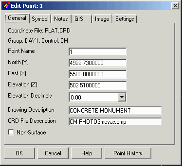
The dialog has several tabs. On the General tab, the name of the
coordinate file for the point is displayed at the top along with
any point groups that contain this point. The Elevation Decimals
setting for the point elevation label. Both Drawing Description and
CRD File Descriptions are displayed. When a change to the Drawing
description is made, this change will not be reflected in the
coordinate file. This allows the change of a description that is
defined in the Field to Finish (fld) table for a particular code.
If a change is made in the CRD File description, it will be
reflected in the coordinate file. Take note that if the CRD file
description is changed, running Field to Finish will change the
definitions for the point changed. If you change the point number
to a number that already exists in the current CRD file, and point
protect is ON, you will be prompted whether to overwrite or
renumber. The Non-Surface toggle controls whether this point is
filtered out in surface modeling with Triangulate & Contour.
This Non-Surface setting is the same that the Non-Surface Points
routines use in the 3D Data menu. The properties that you modify,
with the exception of Drawing Description, will update the current
CRD file. All modifications will update the point screen
entities.
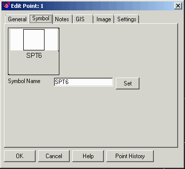 To change the symbol, go to the Symbol
tab and either type in a new symbol name in the edit box, or choose
the Symbol or Set button where you can choose from a list of
symbols from the Symbol Library.
To change the symbol, go to the Symbol
tab and either type in a new symbol name in the edit box, or choose
the Symbol or Set button where you can choose from a list of
symbols from the Symbol Library.
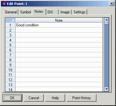 On the Notes tab, you can edit notes
for the point. These notes are free-form additional descriptions
for the point.
On the Notes tab, you can edit notes
for the point. These notes are free-form additional descriptions
for the point.
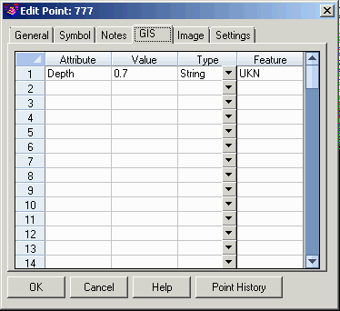 On the GIS
tab, you can edit GIS attributes for the point. These GIS
attributes are only available for CRDB format coordinate files. See
the GIS Data section of the manual for more information on the CRDB
GIS data.
On the GIS
tab, you can edit GIS attributes for the point. These GIS
attributes are only available for CRDB format coordinate files. See
the GIS Data section of the manual for more information on the CRDB
GIS data.
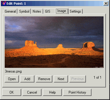 The Image tab shows any images
assigned to the point. The Open function will open the image in the
image program set in Windows for the image file type. The Add and
Remove functions are to add and remove images assigned to the
point. The Next and Previous buttons are for selecting different
images when the point has multiple images.
The Image tab shows any images
assigned to the point. The Open function will open the image in the
image program set in Windows for the image file type. The Add and
Remove functions are to add and remove images assigned to the
point. The Next and Previous buttons are for selecting different
images when the point has multiple images.
The Settings tab has a control for the number of decimals to use
in the dialog.
Selecting the Point History button will bring up another dialog
box that displays the point history of the point chosen. A history
of the point will be listed, but only if, under General Setting,
the Maintain CRD History File had been set to ON (selected) for the
coordinate file that you are working with. With the CRD History
feature of Carlson, all point changes can be rolled back.
You may also choose to use the CAD DDATTE command to
change the attributes of a point. If you do this, then the CRD file
will not be updated and if you change the elevation attribute, the
point will not change its current Z location.
Pulldown Menu Location: Points
Keyboard Command: editpnt
Prerequisite: Carlson points