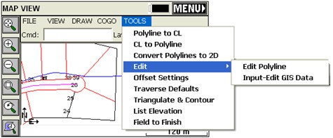
The Tools menu is found next to the COGO menu in MAP view. Below you will find each feature described.
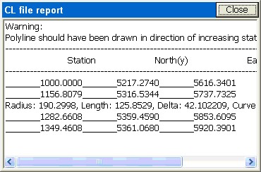
Polyline to CL (P2CL):
Converts any polyline into a centerline file for use in the Roading commands and in Centerline, Curve and Offset Stakeout. You will be prompted for starting station and you will obtain a centerline report. Use Reverse Polyline (RV) and repeat the command to change the direction of the stationing.
CL to Polyline (CL2P):
This command draws a POLYLINE entity using the data from a centerline file. You can practice this command by selecting the file Demo.cl, provided with the program.
Convert Polylines to 2D (C2D):
Pick any 3D polyline and convert it to 2D (elevations of vertices are set to 0).
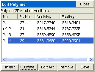
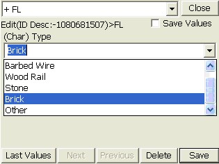
Edit - Polyline (EDP):
Remove vertices, insert vertices and update (alter) the coordinates of any vertex. For example, if we pick the centerline that was used above to interpolate points using Interval along Entity, we obtain the edit dialog.
Edit - Input-Edit GIS Data (EGIS):
This command allows you to input or to edit GIS attributes associated with an entity. The user can select the entity from screen or for the case of a closed polyline he can pick inside the area defined by that entity.
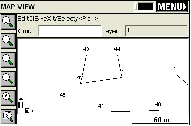
Only polylines (open or closed) can be selected. This command does not apply to attributes associated with points (use List Points to edit point attributes). Attributes are associates with points, polylines and polygons (closed polylines) either through use of feature codes or by importing shapefiles. If a polyline is closed, you can use the Pick option and simply pick inside its interior. This “fence” description included a “fence type” attribute, which now can be edited.
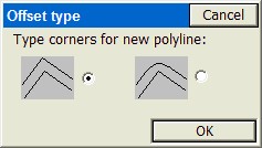
Offset Settings (OF):
This command allows you to set the type of corner that SurvCE should create when offsetting entities.
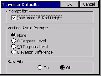
Traverse Defaults (TD):
This sets the elevation prompting (none, zenith, vertical, elevation difference), within the Traverse and Sideshot commands within the MAP view. Also enables a prompt for Instrument and Rod Height. Default setting is no instrument or rod heights and no vertical angle prompting, so inputs are simplified as angle/bearing code, angle/bearing, distance, description, point number. Traverse and Sideshot entries within the MAP screen are stored to the RW5 file.
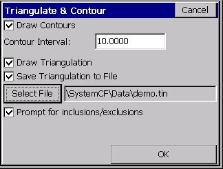
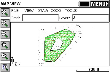
Triangulate & Contour (TRGC):
Triangulate and Contour can create a final contour map based on the user given data: points, polylines. This function has many options which are specified in its dialog box. The routine will prompt also for inclusion and exclusion polylines. To delete entities drawn with this command, turn off all of the drawing options and process.
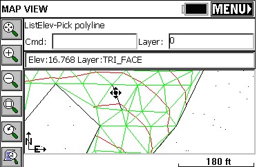
List Elevation (LELV):
This command allows the user to pick on an entity and retrieve the elevation of that point.
Field to Finish (F2F):
This command will redraw the linework created with Feature Codes based on the current coordinates of the points. So if a GPS file was “processed” using a new localization, or a total station survey was adjusted, the existing linework made by use of Feature Codes will erase and redraw by connecting to the adjusted coordinates. In this way, polylines on the MAP screen created by field surveying will be redrawn to recapture their association with the adjusted point coordinates.