This routine will report a cut/fill in comparison with your current location to a design surface at any location within a project. It has the capability of referencing the position of the shot to a project centerline for a report of station and offset and can also be used with a light bar.
Pre-Requisites and Procedures
There are five types of data that can be used to define the design surface.
- Grid File: .GRD file that can be created with various software packages such as SurvCADD, Carlson Survey, or Autodesk Field Survey. You must transfer this file to the collector via the File Transfer routine prior to running this command.
- Triangulation File: .FLT file that can be created with various software packages such as SurvCADD, Carlson Survey, or Autodesk Field Survey. You must transfer this file to the collector via the File Transfer routine prior to running this command. Note that triangulation files can be imported from LandXML or DXF format using the command File, DTM Import, found in the Map screen.
- Elevation: Known elevation that you specify in the Set Elevation field.
- Road Design: Requires a Template, Centerline and Profile file at a minimum, and can utilize superelevation and template transition files.
- Section: Requires a Cross Section file and a Centerline file.
- Select Type of Surface Model: Allows the user to specify the type of surface to be used. See the reference paragraph above. To use a Grid or Triangulation file, select the appropriate button on the screen and press ok. In the file dialog box, select the desired file and press ok.
- Set Elevation: This option is available when the Elevation method is used for defining the surface model. Enter the desired elevation of your surface in this field.
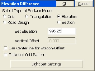
- Vertical Offset: This is used in conjunction with grid, triangulation, roading and section files. It allows the user to vertically offset the surface (as defined in the file) by the amount specified in the box.
- Use Centerline for Station-Offset: This allows the user to specify a horizontal alignment file (.cl file) for reporting station and offset of your current location to the reference alignment. With total stations this is reported whenever a shot is taken. With GPS or Robotic Total Stations, with tracking on, your current position is updated in real time as the rover or prism is moved. This option is available with all three types of surface models.
- Stakeout Grid Pattern (GPS Only):The first prompt asks if you want to use the last stakeout pattern. To make a new pattern, you specify, in effect, the lower left corner (“left side” option) or the lower right corner (“right side” option) of a rectangle, and specify the starting point, direction point. Shown in the next figure below is a 10x10 layout at 50’ interval (400 points would be staked!). The number of cells in the grid ranges from 1x1 to 20x20, and are laid out in a grid beginning at the starting point going towards the direction point.
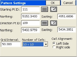
The program will then show the nearest grid point to your GPS position.
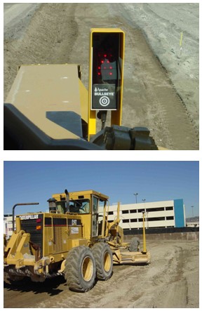
- Light Bar Settings: This button opens allows you to specify parameters for enabling the light bar, setting the grading tolerance and specifying the COM port. Two light bars are supported: Mikrofyn and Apache.
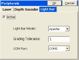
SurvCE can actually drive the grading process, as shown below, where an Apache light bar is used on a motor grader.
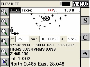
Pressing OK from the main Elevation Difference screen will first prompt the user to load the surface files involved (unless elevation method was selected). Then, when OK is chosen, the following ELEV DIFF screen comes up. This screen provides the user with a plan view of the project. When a shot is taken, cut or fill from the current vertical location to the design surface is reported in the lower left portion of the screen. The computed design surface elevation for your current location is also reported.
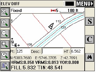
Options on the right side of the screen are shown below:
Read (R): This allows the user to take a shot without storing it to the job file. Cut or fill is immediately reported. This button is not present with GPS.
Store (S): This button immediately reports cut or fill and stores the current shot to the job file. Pressing the enter key will simultaneously read and store your current shot as well. Shots store like topo shots, and respond to the setting in Height/Description Prompt on Save, within Configure Reading.
El: This allows you to set the elevation.
Configure (C): This takes the user to the Configure Reading dialog that is standard throughout the program.
Monitor/Skyplot: If using GPS, this is the last button on the right side of the map screen from top to bottom. This "binocular" button opens the Monitor/Skyplot dialog.