Tools Menu: Edit Process Raw File
11.10 C&G Editor
FUNCTION:
The
Edit Process Raw File
routine is used to edit and re-run traverse courses.
It is also used to compute closures and do traverse adjustments. The
C&G Editor option uses the raw editor common to C&G Software products.
Activate
the C&G Editor by
picking from the Tools
menu, or by pressing
[Alt][T],
[E], [C].
 |
By default, "Sight" Survey uses the Carlson Raw Editor
and .RW5 files for Traverse Closure, Deed Check, and
adjustments (including adjustments other than Network Least Squares).
The C&G Raw Editor is available for data transfer and Network
Least Squares. If you want to transfer a C&G raw file (.CGR)
from your collector and then run a Compass, Crandall,
Transit, or No Adjust, you need to download the .CGR file,
then open the Carlson Raw Editor (see
Section 11.11) and import the C&G file (using
Tools > Import Raw Data > C and G). |
The
SurvNET (or C&G) Editor in "Sight" Survey is a sub-set of the full CG Editor program common to C&G
software. This subset has been designed to work with SurvNET. If you
are familiar with the full CG Editor, you may find it lacks certain features
and file support. For example, this sub-set editor can only handle C&G Raw
file (.cgr), and not Map Check files, Cross-Section files, or Template files.
File support
The
CGEditor can create and/or edit C&G Raw Data Files (.cgr). Raw data files
contain information pertaining to a field traverse. These files are
typically downloaded from the data collector and converted to the C&G raw data
file format.
Opening Files
To open
an existing file, select File > Open. You can then use the file
dialog box to browse to the desired file. Click on the desired file to
highlight it then click the [Open] button.
Creating
Files
To
create a new file, select File > New. A spreadsheet type window
will open but, since it is a new file, it will not contain any data in-put lines
yet. You must first add the desired records before typing in the data.
Cut and Paste
operations
With
the CGEditor you can use the Edit menu to cut and paste or you can use
the standard Windows keyboard shortcuts for cutting ([Ctrl][X]),
pasting ([Ctrl][V]),
copying ([Ctrl][C])
and undo ([Ctrl][Z]).
You simply highlight the data then use the shortcut keys or the menu item to
issue the command. To highlight a field simply click on it or, to
highlight a record, click on the first column in the record (labeled either
Type or Row). To highlight several records use the left mouse
button to click on the first column then hold down the mouse button and move the
mouse until the desired records are highlighted then release the mouse button.
Menu Shortcut
Keys
Please
note that many menu items have short cut keys that make it unnecessary to
actually access the menu to accomplish a given task. These short cuts are
noted on the menu and require that you press and release two or three keys at
the same time. The first one or two keys will be one or a combination of [Ctrl],
[Ctrl], or [Ctrl]
and the last key is a letter. For example, the Copy menu item is
specified in the menu as Copy Ctrl + C. This means that when you press
and release the [Ctrl] and [C]
keys at the same time, the copy command will run.
Automatic
conversion of distance during data entry
You can
automatically convert a distance entry’s units by adding a “*”
after any distance entry. If Distance Units are set to Feet in the
Settings dialog, the entry is assumed to be in meters and is converted to
feet. The opposite is true if Distance Units are set to Meters.
C&G Raw Data
Files
• The
raw data file contains data pertaining to one or more traverses.
• There
are three basic types of traverses:
• Closed Loop Traverse
• Closed Traverse Beginning and Ending at Known
Points
• Open Traverse and Side Shots
•
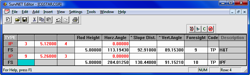
Figures 1, 2, 3 and 4 show illustrations of each of these traverse types. Below
each illustration you will also see the accompanying raw data as seen in the
CGEditor.
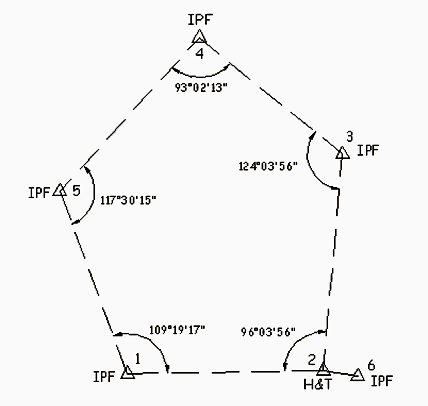
Figure 1 - Closed Loop Traverse.
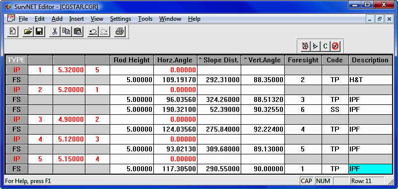
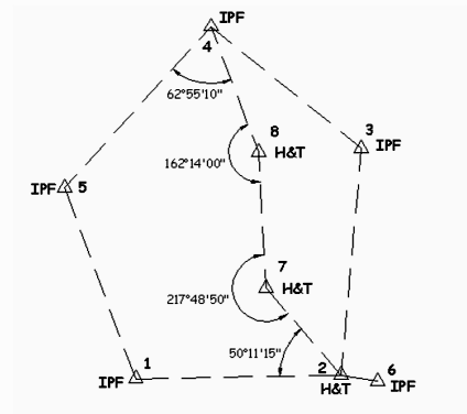
Figure 2 - Closed Traverse Beginning and Ending on
Two Known Points.
Figure
2 shows a closed traverse beginning on two known points (1 and 2) and ending on
two known points (4 and 5). With this type of traverse, both a linear and
angular closure can be calculated.
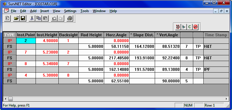
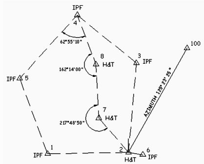
Figure 3 - Closed Loop Ending on One Known Point.
Figure
3 illustrates a traverse that begins on two known points, or a single known
point and a back sight azimuth, and ends on one known point. In this case it is
only possible to calculate a linear closure.
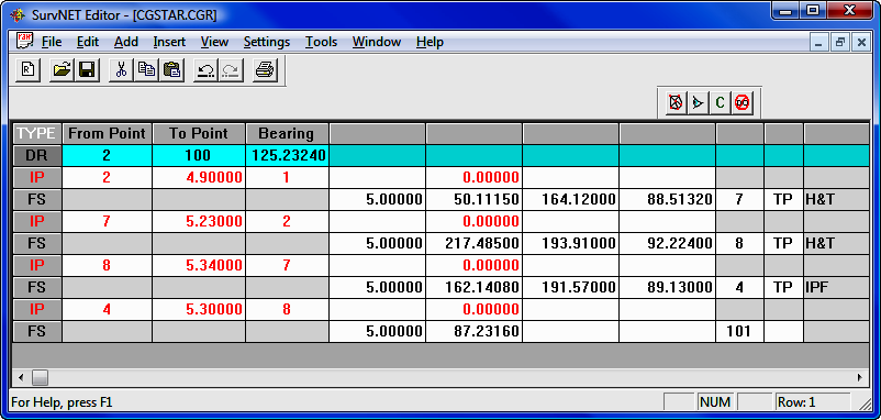
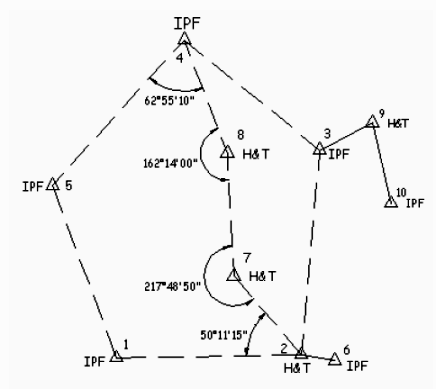
Figure 4 - Open Traverse with Side Shots
Figure
4 shows an open traverse with side shots.
|
|
NOTE: The data shown in the
CGEditor views accompanying the four illustrations include instrument
height (HI) and rod height entries. However, if you have
elevations turned off, these entries are optional. Also, the
examples use single distance and angle entries but multiple measurements
are allowed. |
In
these figures each traverse has been placed in a separate raw data file.
However, with the use of special codes you can combine multiple traverses in a
single raw data file.
ENTERING AND EDITING TRAVERSE DATA
In the
CGEditor “Raw Data” refers to unadjusted field traverse data, typically
downloaded to the PC from a data collector. C&G raw data files have the
extension .CGR.
Creating or
Opening a Raw Data File
To
create a new file or open an existing file click on the File menu then
either click on New or Open. If you click on Open you
will then see a file dialog. Browse to the directory where you wish to
work and select an existing file having a file type of C&G Raw Data File (*.cgr)
and click the [Open] button.
If you
are creating a new file, an empty file will be shown in its own spreadsheet
window within the editor. If you are editing an existing file, the data
from the file will appear in a similar spreadsheet window. It is possible
to have multiple documents open at the same time. So you could create a
new file and open an existing file in the same editing session and each would
appear in its own window in the editor. You can have as many new and/or
existing files open as your project demands.
A new
file will be named CGRaw#, where # is an integer value that
increments from 1 whenever you open a new file. For example, if you opened
three new files at once, your jobs would be named: CGRaw1; CGRaw2; and CGRaw3.
These job names will be used until you rename the job using the Save or
Save As command from the File menu.
Settings
Before
entering any data you should check the current settings. Click the
Settings menu item then click Raw Data File to review and/or change
the current settings. (See the Settings menu section later in this
chapter.)
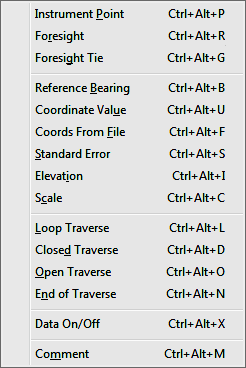
Traverse Data Entry
A line
or row in the raw data file is referred to as a record and each item of data in
a record is referred to as a field. There are several types of records
that you may use in a raw data file:
●
Instrument Point
●
Foresight
●
Foresight Tie
●
Reference Bearing
●
Coordinate Value
●
Standard Errors
Control
Measurement
Setup
●
Elevation
●
Scale
●
Loop Traverse
●
Closed Traverse
●
Open Traverse
●
End of Traverse
●
Data On/Off
●
Comment
The
type of data required for each of these types of records varies. Some
require no data entry and are only “flags” to signify the beginning or ending of
a series of records; others require only one field to be filled out; while
others require several fields of data.
Adding and Inserting new records
When
creating a new file, to begin entering data you must select from the Add
or Insert menus to create the first blank record and begin data entry.
Depending on what type of record you are editing, when you press [Enter]
for the last field in the record, the following record will be added
automatically.
|
|
NOTE: If the Add
and/or Insert toolbars are not showing, click on the View
menu then click on the toolbar you want to turn on.
|
�
When
you click on one of the Add menu items or toolbar icons, an empty record is
added to the end of the file. If you click on one of the Insert menu items
or toolbar icons, an empty record is inserted above the currently active record
or field. To make a record the currently active record, just click on one
of its fields.
Moving from field to field
While
entering data, to move to the next field, press the [Enter] or the
[Tab] key.
To move to the preceding field press the [Esc] key or both the
[Shift] and [Tab]
keys at the same time.
Instrument
Points
The
first record of a raw data file is often an instrument point. Add or
insert a blank record using the menus or toolbars. Fill in the following
fields in the new instrument point record:
● Inst. Point: Enter the point
ID of the instrument point.
● Inst. Height (or HI): Enter
the instrument height. This may be either the distance from the IP on the
ground (“Plus-up”) or the actual elevation of the instrument, depending on how
the data is to be reduced. This field will only be active if elevations
are on. (See the Settings section in the Entering and Editing
Traverse Data section of this chapter)
● Backsight: Enter the point ID
for the backsight.
● Rod Height: Enter the rod
height. This field will only be active if elevations are on. (See
the Settings section in the Entering and Editing Traverse Data
section of this chapter)
● Horz. Angle: Enter the
instrument’s initial horizontal angle reading at the back-sight. When
doing an azimuth traverse, no entry is required here.
|
|
NOTE ON DOUBLED ANGLES: Doubled
angles require two (2) Instrument Point records. Each new
instrument setup requires a 0 to the back sight. The first angle
to the foresight is the single angle. This angle is locked into
the gun and the back sight is retaken. The second angle to the
foresight is the doubled angle. You may also double angles to side
shots. |
Slope Distance and Vertical Angle or Horizontal Distance and Vertical Distance
to the Back sight: Enter
the appropriate distance and/or angle. A blank is assumed to be a zero.
|
|
NOTE: When the Slope Dist/Vert
Angle or Horz. Dist/Vert. Dist. column headings are preceded
by a “^” it indicates that a record inserted before the current
record (or added after the current record) will have the same type of
distance entry mode. For example, if the heading shows ^Slope
Dist and ^Vert Angle and you insert a record, the new record will be
in the Slope Dist/Vert Angle distance entry mode. You can
change this by clicking on one of the distance headings to remove or add
the “^”. If the “^” is not present it means that the
inserted or added record will have the opposite distance entry mode than
does the current record. |
● If, after entering the data in the
last field of a given Instrument Point record, you press the [Enter]
or [Tab] key, a Foresight record will
automatically be created. If you want to change this newly created blank
Foresight record into an Instrument Point record, press the [Esc]
key. If you are at the end of the file, pressing [Esc]
again will delete this new Instrument Point record.
Foresights
After
entering the data for the last field in the Instrument Point record,
press [Enter]. This will cause a
Foresight record to be created below it. This record will contain the
following columns (the explanations of several of these columns are as described
for Instrument Points, only differences will be noted here).
• Rod Height: This column is
only active if elevations are on.
• Horz Angle: Enter the
instrument’s horizontal angle reading at the foresight point. Enter a
positive value for a clockwise angle and a negative value for a
counter-clockwise angle. This entry may be blank if you are entering only
the distance readings to the foresight.
• Slope Dist/Vert Angle or Horz
Dist/Vert Dist: Enter the distance data for the foresight point.
• Foresight: Enter the Point ID
for the foresight point.
• Code: Enter the code for the
Foresight Point. This column is only active if Code is on. (See
Settings in this section.)
• Description: Enter the
description for the Foresight Point. The number of characters you are
allowed to enter is set in the Settings under Description Length.
If you enter an integer code here and the
Translate Raw Descriptions Using Description Table is checked in the
Settings and a matching description number is found in the description
table, then the description from the table will replace the integer value you
entered in the Description field. The integer value you entered
will then be moved to the Code field.
• Side Shots: Side shots should be
placed within the block of foresights immediately following the instrument point
record for the instrument point from which they were shot. You may append
side shots to the end of a traverse file, but they must be preceded by a begin
open traverse record.
Foresight Tie
In some
cases, you will need to tie to an existing traverse. You use a
Foresight Tie record to do this. This record is used in the reduction
process to determine what known point you are tying into. It is necessary
if there are side shots taken at the last setup along with the tie point.
In a
closed traverse, you must end a traverse by occupying a known point and turning
an angle to a second known point. The second known point is the tie point.
Reference
Bearing
You may
Add or Insert a reference bearing or azimuth (depending on whether
Direction is set to Bearing or Azimuth in Settings).
Reference bearings are entered in the following format:
<pointID><dash><pointID><space><bearing>
For
example: 23-45 145.34568 specifies that the
bearing from point 23 to point
45 is N 45° 34’
56.8” E.
Coordinate
Value
You can
use either the Add or Insert menus or toolbars to create a new
coordinate record. You can then hand enter known coordinates for a point.
Coordinates can be used as a reference point during the reduction process.
Coordinates
from a Coordinate File
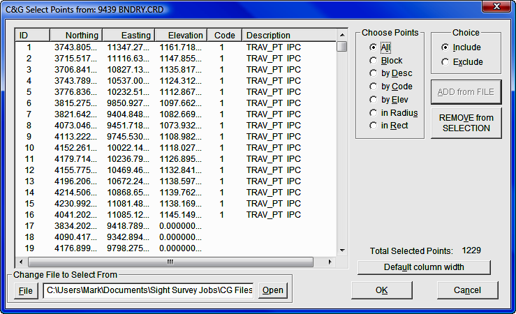
Instead
of hand entering coordinate points, you can insert coordinate records from an
existing coordinate file. Click the Insert menu, then pick the Coords
From File menu item.
Standard
Error
You can
provide standard error information for the Network Least Squares reduction
program by inserting standard error records. Standard error records
specify the standard error value for a given type of measurement. Standard
errors should be in specified in units that are consistent with the units of the
type of measurement to which they are being applied.
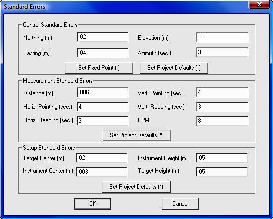
When
using the SurvNET program, you can enter a “*” for any entry to use the
SurvNET project defaults. For more information on the values allowed and
the uses of standard errors, please refer Network Least Squares in
Section 11.12.
Elevation
You can
specify the elevation for a given point ID using an Elevation record.
Scale
You may
specify a scale factor in a Scale record. A scale factor is a decimal number.
You may enter as many scale factors as you wish. A scale factor will be
used until another is encountered. Scale factors should be placed
before an Instrument Point record.
Multiple
Traverses
If you
are combining more than one traverse in a single raw data file, you must
separate the traverses with special records.
After
inserting or adding a begin traverse record, you may type in a comment regarding
the traverse in the Comment column. You may also specify the order in
which the traverses are to be processed by using the first part of the
Comment field. Please see
Traverse
Reduction Order below for more details.
The
following records can be used to indicate the beginning and ending of a given
type of traverse:
Loop
Traverse: Indicates the beginning of a loop traverse. A loop
traverse begins and ends at the same point. If you wish to add a comment
to identify the traverse in some way, just type it in the Comment column.
Closed Traverse: Indicates the beginning of a closed traverse. A
closed traverse ties into known points at both ends. If you wish to add a
comment to identify the traverse in some way, just type it in the Comment
column.
|
|
NOTE: If you are running a
Closed Traverse, a reference azimuth must be placed at the last
instrument point if you wish to adjust the angular error.
|
Open
Traverse: Indicates the beginning of an open traverse. An open
traverse is a group of side shots. If you wish to add a comment to
identify the traverse in some way, just type it in the Comment column.
End
Traverse
Signals the end of the data records for any of the traverse
types.
Data
On/Off
This is
a C&G specific record recognized by the Network Least Squares program. When a Data On/Off record is encountered during
processing, the records following it are ignored until another Data On/Off
record is encountered. This can be very helpful in finding incorrect data or
just processing a portion of the data in a file.
Comment
Inserts a comment line above the current active line.
Comment records may contain text or numbers in any combination. Comment
records can be used anywhere in the raw data file and are for any notes or other
data the user wants to include in the file. Comment records are ignored
when processing the raw data.
Traverse Reduction Order
The
order in which the traverses appear in the raw data file is typically not
important. Traverses are processed in the order in which they appear in
the file. Traverses may be entered in a sequential order or you may embed
one traverse within another.
However, if the coordinates computed from one traverse are needed for the
reduction of another traverse, then order IS important. If this condition
is true for a raw data file and the traverses have NOT been placed in the raw
data file in the correct order, then you need to specify a Traverse Order
Number for each traverse in the file.
|
|
NOTE: If you specify
Traverse Order Numbers, the traverses in the file will be reduced in
the order of their Traverse Order Numbers.
|
Traverse Order Numbers: Each Loop Traverse, Open Traverse
or Closed Traverse comment field can contain a Traverse Order Number.
|
|
NOTE: The Traverse Order Number
must be an integer and must appear as the first entry in the Comment
field separated from the remainder of the comment by a space. For
example, the comment field of a Loop Traverse record having a
Traverse Order Number of 3 should look like this:
3 this is a
comment
|
All
begin traverse records MUST have a Traverse Order Number if any one of
them has a Traverse Order Number. However, the Traverse Order Numbers in a
given file must begin with 1 and continue sequentially. You may not
duplicate a Traverse Order Number for any begin traverse record in a given file.
 |
IMPORTANT NOTE: Reducing a
raw data file having Traverse Order Numbers that violate any of
the above specifications will have unpredictable results. Error
messages during the reduction process may not reflect the fact that
improper Traverse Order Numbering is actually the root cause of
the problem. |
Data
On/Off: This is a C&G specific
record recognized by the Network Least Squares program and the CGSurvey traverse
reduction features. When a Data On/Off record is encountered during
processing, the records following it are ignored until another Data On/Off
record is encountered. This can be very helpful in finding incorrect data or
just processing a portion of the data in a file.
Comment: Comment records may contain text or numbers in any
combination. Comment records can be used anywhere in the raw data file and
are for any notes or other data the user wants to include in the file.
Comment records are ignored when processing the raw data.
Editing a Raw Data File
The
following sections describe the CGEditor menus and the features each offers.
File
Menu
Many of
the following File menu items will be familiar to experienced Windows
users:
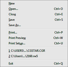
File > New
Allows you to create a new raw data file.
File > Open
(Ctrl + O)
Brings up the Open File dialog box so you can
select and edit an existing file.
File >
Close (Ctrl + E)
Closes the current data file. If more than one
file is open, the file that is currently being worked on will be closed.
File > Save
(Ctrl + S)
Saves the current file.
File > Save
As
Allows the user to save the current file to a file having a
different name.
File >
Print (Ctrl + P)
Allows the user to print a copy of the currently
active file.
File >
Print Preview (Ctrl + W)
Allows an on-screen preview of how the
current file will look when printed.
File >
Print Setup (Ctrl + U)
Brings up a standard Windows print preview
dialog box for selecting which printer to use, what size paper to use, the page
orientation, etc. The dialog layout depends to some degree on the type of
printer you have.
File > Exit
(Ctrl+Q)
Exits the CG Editor.
Edit
Menu
As with
the File menu, the Edit menu is typical of most Windows programs.
Most of
the items in the Edit menu require that either a field within a record,
or the entire record itself, be selected (highlighted) be-fore running the
command. To select a field simply click the field. To select a
record (row) simply click on the first field in the record (under the TYPE
column).
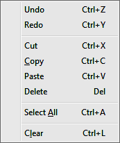
Edit > Undo
(Ctrl + Z)
Undoes the most recent editing action.
Edit > Redo
(Ctrl + Y)
Reverses the most recent undo action.
Edit > Cut
(Ctrl + X)
Cuts the currently highlighted cell or an entire
highlighted record. You may then use the paste command to put the cut cell or
record in another location.
Edit > Copy
(Ctrl + C)
Copies the currently highlighted cell or an entire
highlighted record. You may then use the paste command to put the cut cell or
record in another location.
Edit >
Paste (Ctrl + V)
Allows you to paste any previously cut or copied
cell or record to the currently highlighted location. If entire records are
being pasted and only a field is currently highlighted, the pasted records will
be inserted above the current record. However, if one or more entire records are
currently highlighted, the pasted records will replace the highlighted records.
Edit >
Delete (<Delete> key)
Deletes the currently highlighted field or
record.
Edit >
Select All (Ctrl + A)
Selects all the records in the raw data file.
Edit >
Clear (Ctrl + L)
Empties all entries in the selected field or record.
Add
Menu
The
Add menu allows you to add a record to the current raw data file. The
Add menu item appends the record to the end of the file. The
various types of records are described in the Data Entry subsection of
the C&G Raw Data Files section of this chapter.
(See
the following section - Insert Menu - to insert a record above the
current record.)
Insert Menu
The
Insert menu allows you to insert a record above the current record. The
various types of records are described in the Data Entry subsection of
the C&G Raw Data Files section of this chapter.
(See
the preceding section - Add Menu - to append a record to the end of the
raw data file.)
View
Menu
The
View menu allows you to turn the CGEditor tool bars on or off. If you
open or create a raw data file and do not see the toolbars, use this menu to
turn them on again.
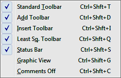
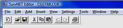
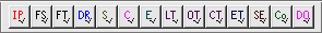
View >
Standard Tool Bar
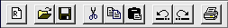
The
above figure shows the Standard tool bar. To issue one of the
commands listed below, click on the appropriate toolbar icon. The icons
represent the following commands (listed in left to right order):
|
 |
Create a new raw file.
|
|
 |
Open a file.
|
|
 |
Save the current file.
|
|
 |
Cut the selected field or record.
|
|
 |
Copy the selected field or record.
|
|
 |
Paste copied or cut data to the currently
highlighted location.
|
|
 |
Undo most recent edit action.
|
|
 |
Redo most recent undo action.
|
|
 |
Print the currently active file.
|
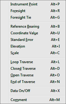
View > Add
Tool Bar
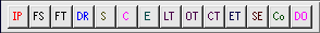
Use the
Add tool bar to add the various types of traverse records to the end of
the current file. The tool bar icons are listed below from left to right:
|
 |
IP |
Add an Instrument Point record
|
|
 |
FS |
Add a Foresight record
|
|
 |
FT |
Add a Foresight Tie record
|
|
 |
DR |
Add a Reference Bearing record
|
|
 |
S |
Add a Scale record
|
|
 |
C |
Add a Coordinate Value record
|
|
 |
E |
Add an Elevation benchmark record
|
|
 |
LT |
Add a begin Loop Traverse record
|
|
 |
OT |
Add a begin Open Traverse record
|
|
 |
CT |
Add a begin Closed Traverse record
|
|
 |
ET |
Add an End Traverse record
|
|
 |
SE |
Add Standard Error records for
Network Least Squares Adjustment
|
|
 |
CO |
Add a Comment record
|
|
 |
DO |
Add a Data On/Off record
|
View >
Insert Tool Bar
Use the
Insert tool bar to insert the various types of traverse records to the
end of the current file.
Notice
that the only difference between the appearance of this toolbar and the Add
tool bar above is the check mark in the lower right hand corner of each icon.
Each icon in the Insert tool bar inserts the same type of record as
described for the similar icon in the
Add tool bar.
View >
Least Squares Tool Bar

The
Least Squares tool bar (or the Network Least Squares tool bar) has the
following four icons:
|
 |
The network icon: Selecting
this icon will start the Network Least Squares program if it is not
already open. If the Network Least Squares program has already
been started, clicking this icon will bring it to the front so you can
work with it. (See
Section 11.12, Network Least Squares)
|
|
 |
The “eyeball” icon: This icon
allows you to bring up a separate window displaying a scaled map of the
current raw data file. (See Graphic View under the View
menu section)
|
|
 |
The “C” icon: Clicking this
icon “turns off” all Comment records. The Comment
records still remain in the raw file, they are just not shown on the
screen. You will find that there are some actions you cannot
perform when Comments are off.
|
|
 |
The "No DO" icon: Clicking
this icon removes all Data On/Off records.
|
View >
Status Bar
When
this menu item is checked, the status bar will display. If you wish to
change the setting just click on the menu item. The status bar is along
the bottom border of the CGEditor window. On the left side of the status
bar a brief help message is displayed when you hold the cursor over such things
as menu items or toolbar icons. It also has indicators that tell you if
Caps Lock or Num Lock are turned on and displays the Row/record
number that is currently active.
View >
Graphic View
Clicking on this menu item brings up a window containing a graphic
representation of the traverse. The traverse lines and points are drawn to scale
using the data from the current raw data file.
As
noted earlier, the Graphic View window shows a scaled drawing of the
current raw file traverse lines and points. The tool bar icons at the top of the
window can be used to move around in the view and change its appearance.
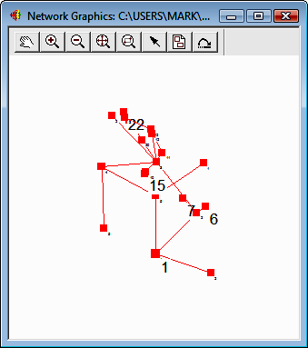
The
icons will be discussed as they appear from left to right:
|
 |
Pan: This works very much
like the AutoCAD Pan command. When you click the hand icon the
cursor changes to a hand. When you click on the graphic screen the
first time you are “grabbing” the graphic. You can then move it to
the proper view and click a second time to “put it down”. You may
repeat this as many times as you wish in order to move around the
drawing. When done with the Pan command, click on the
Pick Point icon (see below).
|
|
 |
Zoom In: Clicking on this
icon causes the graphic image to be enlarged a preset amount. The
zoom factor cannot be configured. If you wish to see a certain
area of the graphic image it is recommended that you click Zoom
Extents then use Zoom Window to view the desired area.
|
|
 |
Zoom Out: As with Zoom In,
Zoom Out reduces the image size a pre set amount. The zoom
factor is not configurable.
|
|
 |
Zoom Extents: Zooms the image
so all points and lines can be seen on the screen.
|
|
 |
Zoom Window: Allows you to
click on two diagonal corners of the rectangular area that you wish to
see.
|
|
 |
Pick Point: Use this icon to
allow you to pick a point on the graphics screen in order to “zoom” to
the first instance of the associated point ID found in the raw data
editor window. This allows you to rapidly and conveniently locate
a given point ID in the data file. This is especially useful in
trouble shooting for errors or other problems in the data that may be
more easily detected in the graphic image than when viewing the raw
data.
When you pick near a plotted point on the
graphics screen its point ID is noted. The raw data file is then
searched for that point ID. The active field in the editor window
is then set to the first instance of that point ID. You can pick
the same location several times to move to the next instance of the
point ID in the file.
If you have a large Pick Radius set
(see Graphic Settings) or are zoomed out, picking a point may
result in more than one point being found. If this occurs, a
dialog box listing the nearby points will pop up. Using the list
box in the dialog choose the desired point ID and press [Enter]
or click [OK] to find the point in
the data file.
Clicking this icon also allows you to turn
off the Pan feature when you are done panning.
|
|
 |
Graphic Settings: Clicking
this icon brings up the Graphic Settings dialog. The
graphic settings dialog allows you to configure the appearance of the
various items that may be seen on the graphics screen.
|
|
NOTE:
The Graphic Settings dialog is
also used for the Network Least Squares program and thus has settings
that are not used by the CGEditor.
|
Points Tab: Control Points, Fixed
Control Points and Floating Points
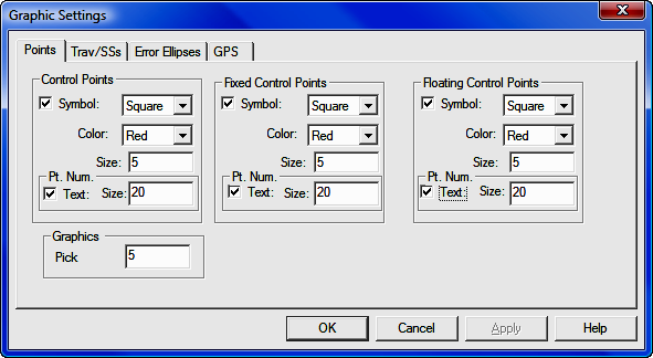
Specify whether the symbols and labels for
any of these points should be shown. Also, if they are to be
shown, specify symbol color, symbol type and point ID label size.
Symbol: Choose Square,
Triangle or Circle from the drop down list.
Color: Choose Red, Green,
Blue, Cyan, Magenta or Yellow from the drop down list.
Size: Specify the size in
feet or meters.
Pt. Num:
Text: Check the check box if
you want the points labeled.
Size: If the points are to be
labeled, specify the label height in feet or meters.
Graphics:
Pick Radius: When you pick near a
point plotted on the graphics screen, the current field in the editor
window moves to the first instance of that point in the current raw data
file. Setting the pick radius allows you to specify how large an area
around the pick point is to be searched for raw data points drawn in the
Graphics View window.
Trav/SSs tab: The traverse,
side shot and azimuth line colors and symbol specifications can be set
here. Except for lines, all the entries on this tab have been
described for the Points tab.
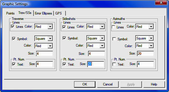
Lines: Check the check box if
you want lines drawn. Set the color of the line using the list box to
the right of each check box.
Error Ellipses tab: These
settings are not used by the CG editor.
GPS tab: These settings are
not used by the CG editor.
|
|
 |
Refresh Graphics: Allows you
to refresh the graphics to view recent changes in the raw data due to
editing.
|
|
NOTE:
For the Refresh Graphics to
reflect recent changes in the raw data file, you must save the file
itself prior to refreshing the graphics.
|
|
View > Comments Off (Ctrl+Shift+C)
This
setting is a toggle to turn comments on or off in CGEditor.
Settings Menu
The
items in the settings menu can be used to configure how the data in the raw data
file will be interpreted and the appearance of that data as seen in the CGEditor.
Settings > Raw Data File
When
you click on the Raw Data File menu item you will see a dialog box that
allows you to specify many of the more important settings related to the
currently open raw data files. You can also set up the defaults that will
be used for newly created raw data files.
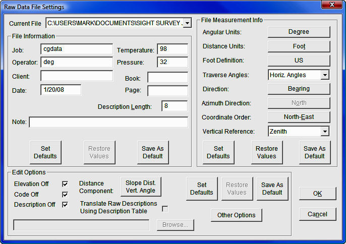
Current File: Set the Current File list box to the file
for which you wish to view or edit the settings. You can also view and
edit the DEFAULT settings for newly created files.
File
Information: This portion of the dialog allows the user to specify job
or project specific information.
-
Job: Enter any name you wish to identify the job or project.
-
Operator: Enter the name of the person who led the field work.
-
Client: The name of the person or company for whom this work
was done.
-
Date: Date in any format you wish to use.
-
Temperature: Temperature at the time the field work was done.
This is for your reference only. May be Celsius or Fahrenheit.
-
Pressure: Atmospheric pressure at the time the field work was
done. For your reference only. May be in any units.
-
Book: Field book number for the field work.
-
Page: Page number in the field book.
-
Description Length: Specify the length of the description field
(# of characters allowed) used in this file.
-
[Set Defaults]: This button sets the items in the File
Information portion of the dialog to the current default values.
-
[Restore Values]: This button allows you to set the
values in the File Information portion of the dialog back to what
they were when you opened the Raw Data File Settings dialog.
-
[Save As Default]: Sets the default values for the
File Information portion of the dialog. These values are used as
the default settings when a new file is created.
File
Measurement Info:
-
Angular Units: Clicking the button to the right changes the
Angular Units from Degrees to Grads or vice versa.
-
Distance Units: Clicking the button to the right changes the
Distance Units from Foot to Meter or vice versa.
-
Foot Definition: Clicking the button to the right changes
the Foot Definition from US to International or vice
versa. This button is only active when Distance Units are set
to Foot.
-
Traverse Angles: Choose one of the items in the list to
specify how the traverse angles were measured: Horiz. Angles;
Azimuths; or Deflection Angles
-
Direction: Specify what type of angle is used to define
the direction of a line. Clicking the button to the right changes the
Direction from Bearing to Azimuth or vice versa.
-
Azimuth Direction: Specify the reference direction for
azimuths. Clicking the button to the right changes the Azimuth
Direction from North to South or vice versa. This
button is only active when Direction is set to Azimuth.
-
Coordinate Order: Clicking the button to the right changes the
Coordinate Order from North-East to East-North or vice
versa.
-
Vertical Reference: Pick one of the items from the list to the
right to specify the reference orientation for measuring vertical angles:
Zenith; Nadir; or Horizontal
-
[Set Defaults]: This button sets the items in the
File Measurement Info portion of the dialog to the current default
values.
-
[Restore Values]: This button allows you to set the
values in the File Measurement Info portion of the dialog back to
what they were when you opened the Raw Data File Settings dialog.
-
[Save As Default]: Sets the default values for the
File Measurement Info portion of the dialog. These values are used
as the default settings when a new file is created.
Edit
Options:
-
Elevation Off: Check this check box to turn off the
Elevation data entry column for this file. This makes data input
more convenient since you do not have to enter any data in the Elevation
column, nor do you have to tab through it. Turning off elevations does
not cause any data to be deleted from the current file.
-
Code Off: Check this check box to turn off the Code data
entry column for this file. This makes data input more convenient
since you will not have to enter any data in the Code column.
Turning off codes does not cause any data to be deleted from the current
file.
-
Description Off: Check this check box to turn off the
Description data entry column for this file. This makes data input
more convenient since you will not have to enter any data in the
Description column. Turning off descriptions does not cause any
data to be deleted from the current file. You can turn the
Elevation, Code and Description data entry columns on or
off by clicking on the column heading.
-
Distance Component: Specify how distances are to be entered.
Clicking the button to the right changes the Distance Component from
Slope Dist-Vert Angle to Horiz. Dist-Vert. Dist. or vice
versa.
-
Translate Raw Descriptions Using Description Table: This check
box is only active if descriptions are on. If you check this check
box, integer codes entered in the Description field will be looked up
in the specified description table (see the following item). If a
matching description number is found in the description table, the code will
be moved to the Code field and the description found in the
description table will be placed in the Description field. If
no matching description number is found, the Description field
remains as entered.
-
Desc Tbl: Click on the Desc Tbl button use a file dialog
to set or change the description table. The description table is used
to set the Description field when an integer number is entered in the
Description field (see the previous item.) If you prefer,
instead of clicking on the Desc Tbl button you can also type in the
full file path in the edit box.
-
[Set Defaults]: This button sets the items in the
Edit Options portion of the dialog to the current default values.
-
[Restore Values]: This button allows you to set
the values in the Edit Options portion of the dialog back to what
they were when you opened the Raw Data File Settings dialog.
-
[Save As Default]: Sets the default values for the
Edit Options portion of the dialog. These values are used as the default
settings when a new file is created.
-
[Other Options]: Click the [Other
Options] button to bring up the Other Edit Options dialog
box.
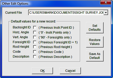
-
Current File: Click on the name
of the file in the file list for which you wish to review and/or specify the
settings. You can also choose to view or edit the DEFAULT
settings.
-
Default values for new record:
Checking the check box for the following items causes CGEditor to
“remember” the most recently entered value in the respective field.
Thus when you insert or add a record containing one of the checked items, it
will be filled in with a “default” value. (The previously used values are
not “remembered” between sessions of the editor.): Backsight ID;
Horz. Angle; Vert. Angle; Foresight ID; Rod Height;
Code; and Description.
-
[Set Defaults]: This
button sets the items in the Other Edit Options dialog to the current
default values.
-
[Restore Values]:
This button allows you to set the values in the Other Edit Options
dialog back to what they were when you opened the Raw Data File Settings
dialog.
-
[Save As Default]:
Sets the default values for the items found in the Other Edit Options
dialog. These values are used as the default settings when a new file
is created.
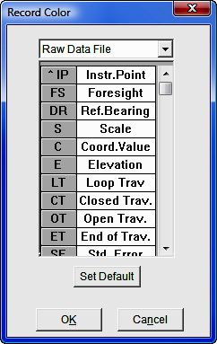
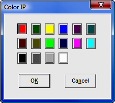
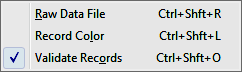
Settings >
Record Color
To set
the color for a given record type, click on the record type and a color
selection dialog will appear.
Click
on the color you want the record type to have. Click [OK]
button to save the color settings and close the dialog. If you click the [Set
Defaults] button, the original program default colors are set.
Click the [Cancel] button to close the
dialog without saving the changes.
Settings >
Validate Records
If this
menu item is checked, all the records in the file will be validated prior to
saving the file. To change the Validate Record setting, just click
the menu item.
If an
invalid record is encountered when saving a file with the Validate Records
menu item checked, you are asked if you want to edit the invalid field, ignore
the error or ignore all errors. If you decide to edit the offending field,
the field will be highlighted and you can edit it and attempt to save again.
Tools Menu
The
Tools menu has several items that can be used to find and replace specific
text in specific types of fields. It even allows you to apply simple
mathematical functions to allow you to edit the data in a group of fields in a
single step.
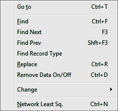
Tools > Goto (Ctrl + T)
Select
this item to go to a certain row (or record) number.
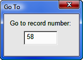
In the
dialog box that comes up, type in the desired row number and press [Enter].
The editor window will zoom to that record and set the current field to the
first editable field in the record.
Tools > Find
(Ctrl + F)
This
dialog allows you to enter a value to find and set the de-tailed search
criteria. Type in the string or number you are searching for in the
edit/list. You can actually type in a word or number or you can use the pull
down list to pick a word or number from a previous search.
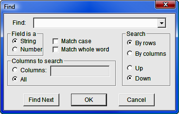
Field is a: Choose what type of data (alphanumeric String or
Number) the field you are looking for contains and what kind of match (Match
Case or Match Whole Word) you wish to use.
Columns to search: The default is to search All columns, but if
you choose the Columns radio button, you can enter a comma separated list
of column numbers. Column numbers begin with one. When specifying
column numbers, the TYPE column is not counted nor can you search it.
Search: You can search By Rows or By Columns
and you can choose to search Up from the current field or Down.
Once
you have specified the parameters for the search, click [Find
Next] to find the first instance of the search string. Continue
to click [Find Next] to find the next
instance of the string.
To just
find the next instance of a string and close the dialog box, you can click [OK].
Tools > Find Next
(F3)
Finds
to the next occurrence of the string previously specified in the Find
dialog.
Tools > Find Prev
(Shift + F3)
Moves
you to the previous occurrence of the string previously specified in the Find
dialog.
Tools > Find Record
Type
Moves
you to the next or previous record of the specified record type.
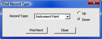
Record Type: Select the record type by clicking [q]
next to the Record Type field, and select your search direction: Up,
or Down. When you have made your selections, click [Find
Next]. You may continue clicking [Find
Next] to locate the next record of the specified type. Click [Close]
to exit the dialog box.
Tools > Replace (Ctrl + R)
When
you click on this menu item, the Replace dialog appears.
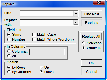
The
Replace dialog allows you to specify a Find value and a Replace
with value. The other fields in the Replace dialog are the same
as the Find
dialog.
You can
view the Find value one instance at a time by clicking [Find
Next], if you decide to replace a given value found just click [Replace].
Alternatively, you can allow the software to automatically replace all the
instances of the Find value encountered in the specified columns in the
raw data file by clicking [Replace All].
Before clicking [Replace All], be sure to
specify whether you wish to replace all the values in the highlighted
Selection or in the Whole File.
Tools > Remove Data On/Off (Ctrl+D)
When
you click this menu item, all the Data On and Data Off records (DO) will be
removed from the file.
Tools > Change
The
items in this submenu allow you to change specific types of fields in the raw
data file.
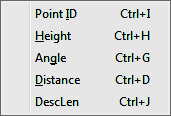
Tools > Change > Point ID (Ctrl + I)
This
menu item allows you to change point IDs for instrument points, back sight
points, or foresight points. You can change individual points one at a
time or you can make a global change. You can specify a value to find and
a value to replace it with. The Change Point ID dialog has several
sections that are similar to the
Replace dialog.
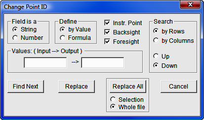
Field is a: You must specify how you want the change command to treat
a point ID field by clicking on the String or Number radio
buttons.
Define: You must specify whether you wish to change by Value or
Formula.
Instr. Point, Backsight, and Foresight check boxes: Check the check
boxes of the types of point IDs you wish to change.
Values: (Formula): It is important to note that the
Values:/Formula: portion of the dialog changes according to whether you
Define by Value or Formula and whether the Field is a
String or Number.
Case 1: Field is a = String
and Define = by Value, or
Case 2: Field is a = Number
and Define = by Value
The title of this section of the dialog becomes
Values: (Input —> Output). In this configuration the command acts
exactly like the Replace dialog except that it only searches the point ID
fields specified. Thus you merely specify the value to search for in the
left hand edit box and the value to replace it with in the right hand edit box.
The [Show Next], [Change]
and [Change All] buttons act exactly the
same as the [Find Next], [Replace]
and [Replace All] buttons in the
Replace dialog
Case 3: Field is a = String and
Define = Formula
The title of this section becomes Formula.
In this configuration the formula acts to add a prefix and/or a suffix to the
existing point ID. Enter the prefix in the left hand edit box and the
suffix in the right hand edit box. If you do not wish to add a prefix or
you do not wish to add a suffix, you may leave either the left or right hand
edit boxes empty. For example, if you entered:
[New]= a [Old] 1
It would change the point ID “456b” to “a456b1”.
Case 4: Field is a = Number and
Define = Formula
The title of this section becomes Formula.
In this configuration the formula adds a specified number to a given point ID.
Enter the positive or negative number to add to a given point ID in the edit box
on the right. For example, if you entered:
[New]= [Old]+ 100
It would change the point ID “456” to “556”.
|
|
NOTE:
When this type of change command is
specified and a point ID containing non-numeric characters is
encountered, it will be skipped and no change will be made to it.
|
Tools > Change > Height (Ctrl + H)
Use
this menu item to change the instrument height and/or rod height. Clicking this
menu item brings up the Change Height dialog.
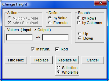
Action: Select the mathematical action you want to perform.
Multiply/Divide: Choose this if you
wish to multiply or divide the height by a given number.
Add/Subtract: Choose this if you wish
to add a specified number to the height or subtract a specified number from the
height.
|
|
NOTE: This section of the
dialog box is only active if the Formula radio button is chosen
in the Define section. |
Define: Select how you
want the mathematical action to be performed.
by Value: If you choose by Value,
this command becomes like the Replace command, except that it acts only
on instrument heights and/or rod heights.
Formula: This allows you to add,
subtract, multiply, or divide the height by a number. (See the Action
and Values/Formula sections.)
Values/Formula: Depending on what you choose in the Action and
Define sections there are several possibilities for this section of the
dialog:
Case 1: Define = by Value (Action
will be inactivated)
The title of this section becomes:
Values:
(Input—>Output)
As noted above the command becomes like the
Replace command, except that it acts only on instrument heights and/or rod
heights.
Case 2: Define = Formula and Action =
Multiply/Divide
The title of this section becomes:
Formula:
The formula will multiply or divide the instrument
height or rod height by the number specified in the edit box. Whether it
multiplies or divides depends on the symbol on the small button. To change
from multiply to divide, or vice versa, simply click on the small button until
the proper symbol (’*’ or ’/’) appears on the button.
Case 3: Define = Formula and Action =
Add/Subtract
Again, the title of this section becomes:
Formula:
The formula will add or subtract the number
specified in the edit box to or from the instrument height or rod height.
Whether it adds or subtracts depends on the symbol on the small button. To
change from add to subtract, or vice versa, simply click on the small button
until the proper symbol (’+’ or ’-’) appears on the button.
Search: Specify the mode of searching through the file. The search begins at
the currently active field.
Instrum. and Rod check boxes: Check one or both of these check boxes
to specify which types of heights are to be searched/changed.
[Show
Next]: Click on the [Show Next]
button to move to the next field that matches the specifications you entered.
[Change]:
Click on the [Change] button to make the
changes specified in the current (highlighted) field in the raw data file.
[Change
All]: Click the [Change All]
button to make the changes specified to all matching fields in the file. Be sure
to specify whether to apply the specified changes to the Selection
(highlighted records and/or fields) or to the Whole file.
[Cancel]:
Click the [Cancel] button to close the
dialog.
Tools > Change > Angle (Ctrl + G)
Choose
this menu item to change vertical and/or horizontal angle fields. Clicking
the Change Angle menu item brings up the following dialog.
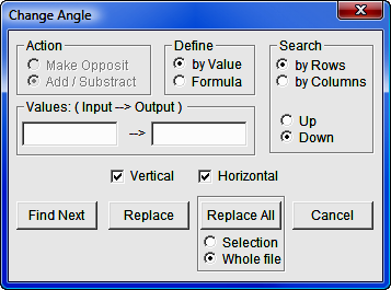
This
dialog is almost identical to the
Change Height dialog. The only differences are that the
Multiply/Divide action is replaced by the Make Opposite action and
you can check either the Vertical or Horizontal check boxes.
If you
choose Define = Formula and Action = Make Opposite, the Formula
section of the dialog is inactivated. This is due to the fact that the
action to be taken is merely to reverse the sign of the angle.
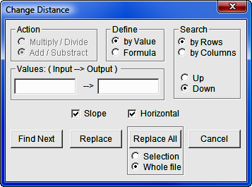
Tools > Change > Distance (Ctrl + D)
As you
can see, the Change Distance dialog is almost identical to the
Change Height dialog.
The only difference is that you can choose to change the slope distance and/or
the horizontal distance by checking the Slope and/or Horizontal
check boxes.
Tools > Change > DescLen (Ctrl+J)
This
command allows you to set the description length for the current raw data file.
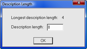
It
displays the Longest description length that was found in the current
records in the file. It allows you to enter the new Description length
you wish to use. If you enter a length less than the longest description,
the descriptions currently in the raw data file that exceed the specified length
will be truncated.
Network Least Squares
This
menu item runs SurvNET, the Network Least Squares Adjustment
program. Please refer to
Section 11.12 for a detailed description of this very powerful
traverse adjustment program.
Window Menu
This
menu contains many of the standard Window menu items found in other programs.
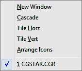
It
allows you to arrange the currently open windows in several configurations.
It has the added functionality of the New Window command which allows you
to have two or more views of a single file.