Lines Menu
7.10 Traverse with Offsets (TO)
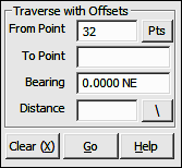
FUNCTION: The Traverse with Offsets routine is used to compute the coordinates of a new point along a line of known bearing and distance from the currently occupied point, and then set perpendicular offsets at the foresight point
Activate the Traverse with Offsets routine by picking from the Lines menu; by pressing [Alt][L], [V], or by typing command TO at any data entry prompt.
From Point: This is the currently occupied point. If you have an occupied point this box will automatically be filled for you. Changing the From Point is equivalent to running the Go To routine (GT - Section 6.06), and will change the BS Bearing, but not the Backsight Point.
|
TIP: Left-click the [Pts] button to select a point from the Point Manager (PM - Section 6.09). Right-click the [Pts] button to select a point from the CAD window (see Picking Points in CAD in Section 2.03). |
To Point: Enter the number of the foresight point or press [+] for the next unused point number.
Bearing: Enter the bearing, angle, deflection or azimuth in your chosen format or recall a bearing between any two points in memory (e.g. 15,20).
Distance: Enter the distance, or recall a distance between two existing points (e.g. 15,20). If you are entering a slope distance, click the [\] button next to the distance field, or press [/] or [\] on your keyboard and to enter your slope data according to the method you specified on the Slope Entry Configuration menu (KS - Section 5.02).
|
TIP: When you are Traversing with Stations, "Sight" Survey will accept a station entry (e.g. 1+37.25) in the Distance field and use the difference between that station and the previous station to compute the actual horizontal distance. |
"Sight" Survey will print the bearing, horizontal and vertical distances from the currently occupied point to the foresight point, and also the point number, ID, Northing, Easting and elevation of the foresight point. The foresight point becomes the currently occupied point, and the reference bearing becomes the bearing just traversed.
If an Offset Table has been defined (OD - Section 6.21) "Sight" Survey will place points at the offsets enumerated in the table. If Automatic Point Numbering (AN - Section 2.10) has been turned on, the computation is fully automatic. If you are manually numbering your points, you will be prompted for each point number until all the table values have been exhausted.
|
TIP: To use the next available point number, just press [+] instead of entering a number. |
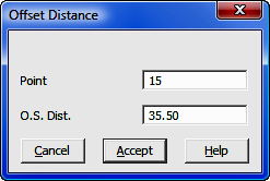
After setting the predefined offset points, or if there are no predefined offsets, you may enter individual offsets through this dialog box:
Point: Enter a number for the offset point or press [+] for the next unused point number. If Automatic Point Numbering (AN - Section 2.10) has been turned on you will only need to enter an offset distance.
O.S. Dist: Enter a positive distance value to offset to the right with respect to the foresight direction. Likewise, enter a negative distance value to offset to the left with respect to the foresight direction. To exit the offset entry, simply click [Cancel] or leave the O.S. Dist. field blank and press [Enter].