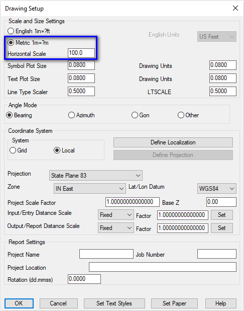
- If you get the Start Page, pick New Drawing.
- If you get the Startup Wizard dialog box, click the Exit button.
- If you are taken directly into CAD, continue as is.
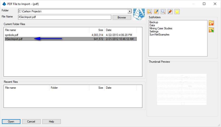
Select the file as shown above and click Open when ready to display the following dialog box:
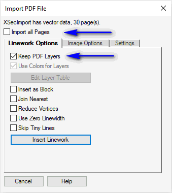
NOTE: For the purposes of this tutorial, we do not need to process all pages within the PDF. Set the values as shown above and click the Insert Linework button when ready. A secondary dialog box displays as shown below:
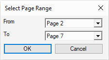
Set the values as shown above and click OK when ready. When prompted:
Pick point to insert PDF: pick a point
Specify rotation angle <0.0>: 0
Specify scale <1.0>: press Enter
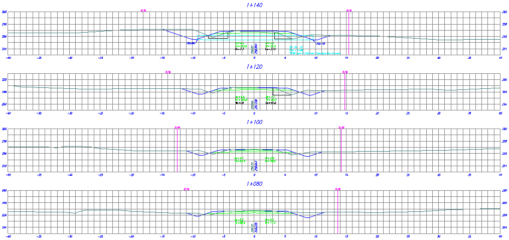
Issue the View -- Extents to display the imported data as shown in the example below:
As is often the case with PDF documents, there may be linework that needs to be joined for efficient processing of the PDF document. Issue the Edit -- Join Nearest command to display the dialog box below:
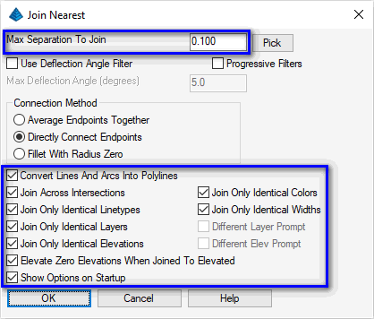
Set the values as shown above and click OK when ready. When prompted:
Select lines, arcs and unclosed polylines to join [Settings].
Select entities: type ALL and press Enter
Select entities: press Enter
Starting point for distance: pick the ENDpoint of the grid line illustrated below
End point: pick the ENDpoint of the grid line illustrated below
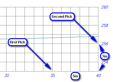
With correct picks (and a proper PDF insertion scale from earlier), the corresponding "X" and "Y" distance units should display on the Command line similar to that shown below:
Delta X = 5.00, Delta Y = 3.00, Delta Z = 0.00
Because the distances picked in CAD match with the distances annotated on the grid sheet, no further action is needed.
NOTE: In the event that further scaling action is needed, two commands that can help overcome this would generally be either:
- Edit -- Scale -- Scale Wizard command, or the,
- Edit -- Align -- 2D Align command.
- Settings -- Carlson Menus -- Construction Menu (commands found in the Roads menu)
- Settings -- Carlson Menus -- Civil Menu (commands found in the Sections menu)
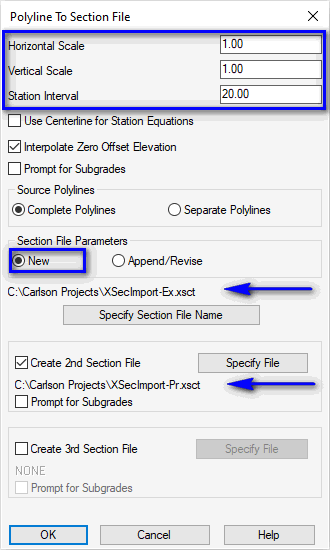
Set the values as shown above paying particular attention to the highlighted items and click OK when ready. A series of prompts will be presented for each cross-section station as illustrated below:
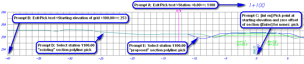
When prompted for the first section:
- Exit/Pick text/<Station <0.00>>: type 1100 and press Enter
- Exit/Pick text/<Starting elevation of grid <100.00>>: type 253 and press Enter
- [int on] Pick point at starting elevation and zero offset of section ([Enter] for none): pick the starting grid elevation at the 0 offset
- Select station 1100.00 [section file 1] section polyline: pick the appropriate polyline
- Select station 1100.00 [section file 2] section polyline: pick the appropriate polyline
The sequence will restart for the next expected cross-section station. Accept the default value or override with a desired value.
NOTE: There will be a starting grid elevation changes starting at 1+300! Make the appropriate adjustment during the prompting!
Pan the drawing to see the next available cross-section station and note its starting grid elevation. Repeat the sequence until you reach station 1+500 and then issue the Exit to complete the conversion process.
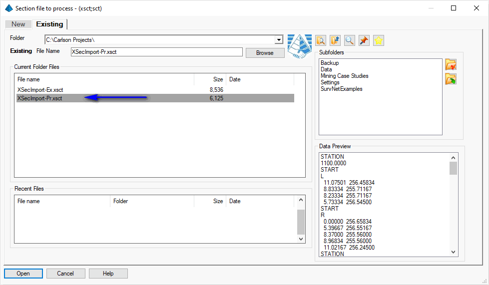
Select the file as illustrated above and click Open when ready to display a dialog box similar to that shown below:
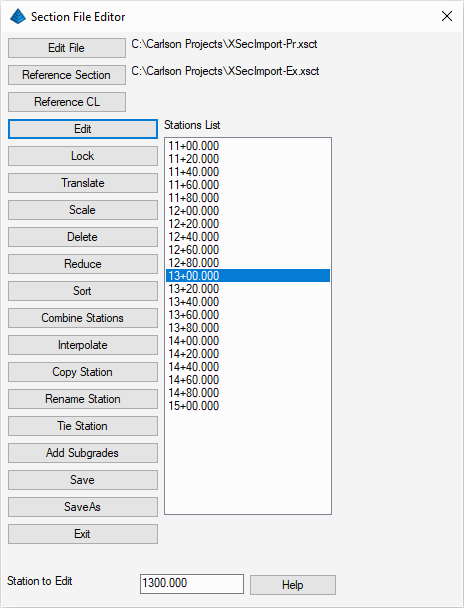
Set the Reference Section file as shown above, highlight a desired to inspect and click the Edit button to display a dialog box similar to that shown below:
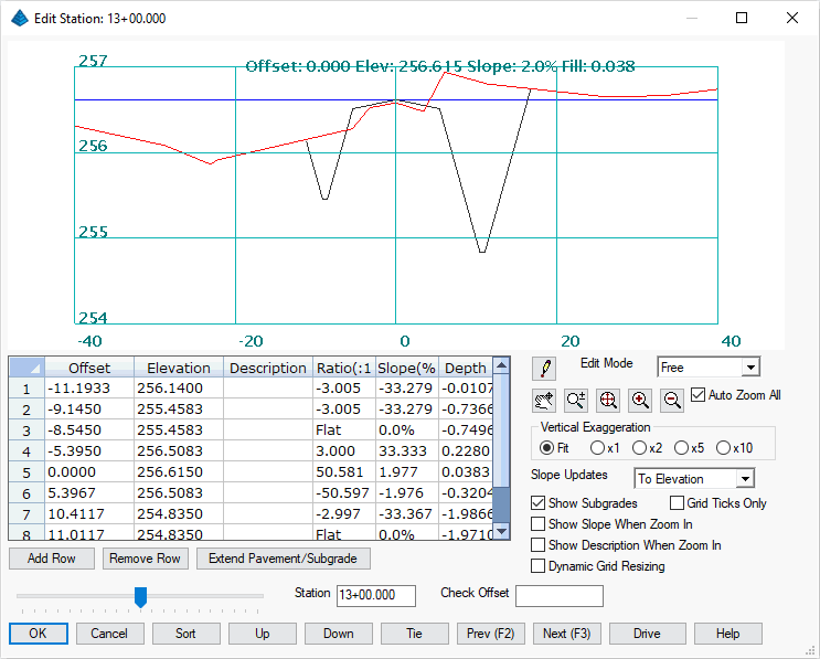
The command shows a graphic preview of the sections along with a spreadsheet of the Edit File values. Explore the remaining controls on this dialog box and click the Cancel button to dismiss it when ready. Click the Exit button to dismiss its parent dialog box.
Section File (Existing Ground) to Read (dialog): select the -Ex section file and click Open when ready
Section File (Final Ground) to Read (dialog): select the -PR section file and click Open when ready
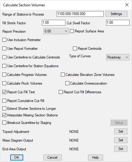
Calculate Section Volumes (dialog): set the values as shown below and click OK when ready
The volumes are calculated and reported, along with the cut and fill end-areas at each station as illustrated below:
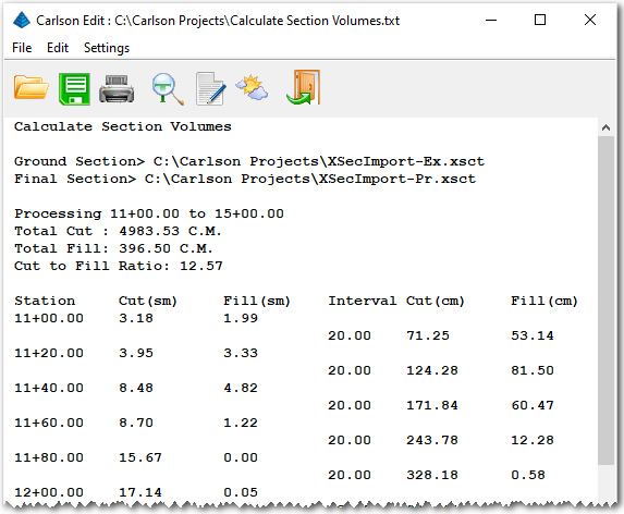
Review the results and click the Exit (Doorway) button to dismiss the report.