- If you get the Start Page, pick Open Files.
- If you get the Startup Wizard dialog box, click the Browse button.
- If you are taken directly into CAD, click File -- Open.
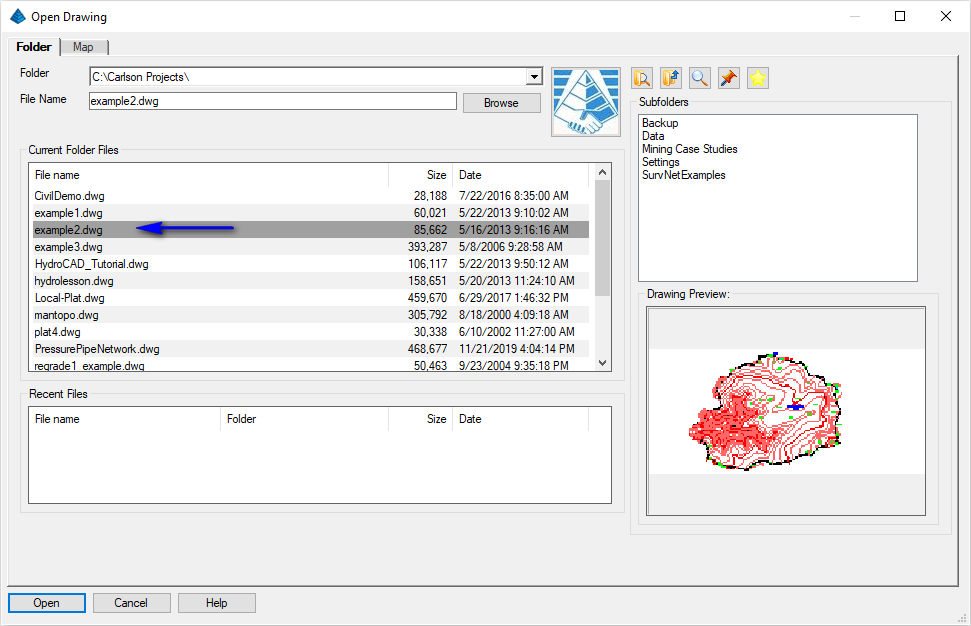
Use the File -- Save As to save a copy named example2-s.dwg. Completing this tutorial will alter the drawing file and by renaming the file from the start, you'll keep the original file intact (allowing you to run through the tutorial a second time if desired). This is also a good practice to keep when working on drawings from 3rd parties.
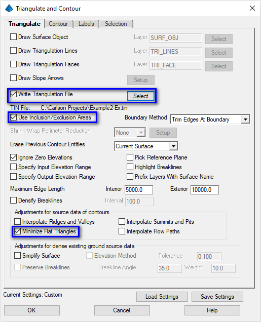
- In the Triangulate tab (as shown above), enable the
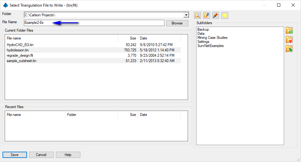
Write Triangulation File toggle and click its
Select button to set the name of a triangulation
(*.tin) file as illustrated below. Click the Save
button on this dialog box so that the results of the triangulation
can be re-used for future purposes. Enable the Use
Inclusion/Exclusion Areas toggle and also turn on the
Minimize Flat Triangles option. This will help
form a more accurate model. Set any remaining options as
illustrated above:
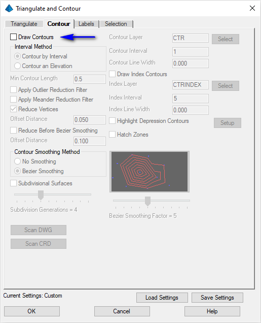
- In the Contour tab, as shown below, toggle off the
Draw Contours option as there are already contours
in the drawing:
Select Inclusion perimeter polylines or ENTER for none.
[FILter]/<Select entities>: pick the BORDER polyline and press Enter
[FILter]/<Select entities>: press Enter
Select Exclusion perimeter polylines or ENTER for none.
[FILter]/<Select entities>: press Enter
Select points and breaklines to Triangulate.
[FILter]/<Select entities>: type ALL and press Enter twice
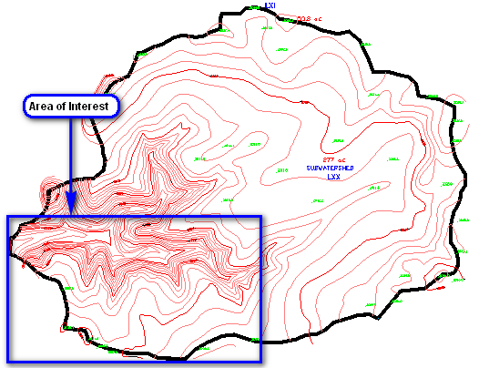
A "TIN" file is written that we'll use again and again. Let's zoom in closer to our desired area of interest. Issue the View -- Window command. When prompted:
Zoom: [In/Out/All/Center/Dynamic/Extents/Left/Previous/Right/Window/ENtity/Scale]<Scale (nX/nXP)>: _w
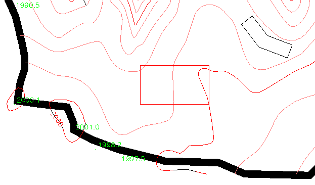
First corner: pick the lower left location of the area of interest shown below
Opposite corner: pick the upper right location of the area of interest shown below
NOTE: Many of the routines below can also be accomplished with the Carlson Survey and/or Construction modules but our focus herein will presume use of the Civil module.
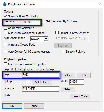
Set the values as shown above making particular note of the highlighted items. Click OK when ready. When prompted:
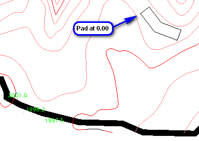
[Continue/Extend/Follow/Options/<Pick point or point numbers>]: pick a first pad location as shown below
[Arc/Close/Distance/Follow/Undo/<Pick point or point numbers>]: pick the second pad location
[Arc/Close/Distance/Extend/Follow/Line/Undo/<Pick point or point numbers>]: pick the third pad location
[Arc/Close/Distance/Extend/Follow/Line/Undo/<Pick point or point numbers>]: pick the fourth pad location
[Arc/Close/Distance/Extend/Follow/Line/Undo/<Pick point or point numbers>]: pick the fifth pad location
[Arc/Close/Distance/Extend/Follow/Line/Undo/<Pick point or point numbers>]: pick the sixth pad location
[Arc/Close/Distance/Extend/Follow/Line/Undo/<Pick point or point numbers>]: press C to mathematically close the pad
 Let's sketch out a
simple rectangular pond bottom. Issue the Draw --
Rectangle (key-in is rectang) and when
prompted:
Let's sketch out a
simple rectangular pond bottom. Issue the Draw --
Rectangle (key-in is rectang) and when
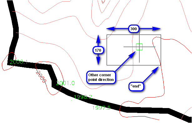
prompted:[Chamfer/Elevation/Fillet/Rotated/Square/Thickness/Width]/<Select first corner of rectangle>: type end (for an endpoint snap) and press Enter
Snap to END of: pick the endpoint on the contour as shown below
Specify other corner point or [Area/Dimensions/Rotation]: type D and press Enter
Enter rectangle length <10.0000>: type 300 and press Enter
Enter rectangle width <10.0000>: type 170 and press Enter
Specify other corner point or [Area/Dimensions/Rotation]: pick a location northwest of the initial point
NOTE: Unlike the 2D Polyline command discussed above which has added functionality permitting you to establish the elevation for the 2D polyline, the Rectangle command will inherit the elevation of the first pick point (a contour in this case).
Let's set the pond bottom polyline to a better target elevation. Issue the Edit -- Change -- Elevations command to display the dialog box as shown below:
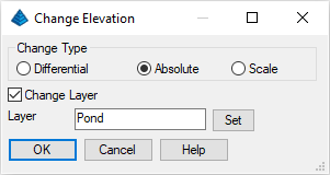
Set the values as shown above and click OK when ready. When prompted:
Select/<Enter Elevation <0.0000>>: if the default value is other than 0, type 0 and press Enter
Select Entities for Elevation Change.
[FILter]/<Select entities>: pick the pond bottom polyline just drawn
[FILter]/<Select entities>: press Enter
Select/<Input another Elevation (Enter to end)>: press Enter
Our resulting polylines should resemble that shown below:
 Set the values as
shown above and click OK when ready. When
prompted:
Set the values as
shown above and click OK when ready. When
prompted:Pick pad polyline: pick the non-rectangular pad polyline (the first that was drawn)
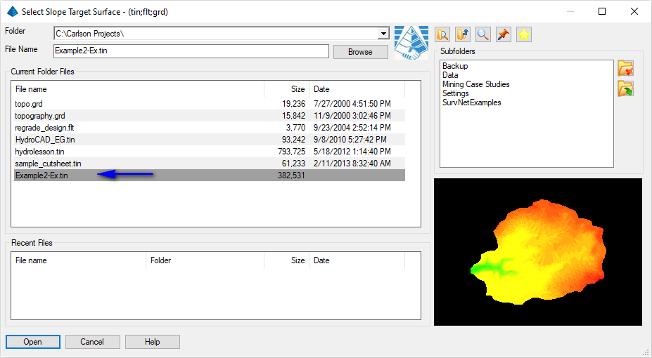
A dialog box similar to that shown below appears. Select the surface model file created earlier and click Open when ready. Prompting will resume:
Fill outslope ratio <3.000>: press Enter
Cut outslope ratio <3.000>: press Enter
Range of existing elevations along pad: 1992.33 to 1995.37 (your values may vary)
Pad elevation <1992.33>: type 1993.5 and press Enter (we'll try to target a balanced Cut vs. Fill)
Slope projections from the source polyline are projected to the surface model file and preliminary results are displayed in the Standard Report Viewer similar to that shown below:
Review the report and notice the Cut Volume will be different from that of the Fill Volume. Click the Exit (Doorway) button to dismiss the report. Prompting resumes:
Adjust parameters and redesign pad [Yes/<No>]? type Y and press Enter
Balance cut/fill [Yes/<No>]? type Y and press Enter
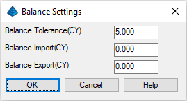
A dialog box similar to that appears. Set the values as shown below and click OK when ready:
The solution is iterated until the balance tolerance is achieved and an updated report similar to that shown belows appears:
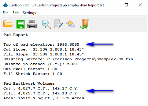
Let's accept the solution. Click the Exit (Doorway) button to dismiss the report. Prompting resumes:
Adjust parameters and redesign pad [Yes/<No>]? type N and press Enter
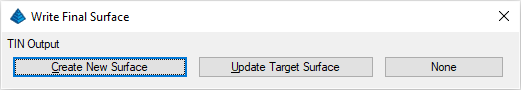
A dialog box as shown below appears, prompting us with an option to commit the Final surface to an external triangulation file which could ultimately be used again in the future. Click the Create New Surface button as shown below:
A secondary dialog box as shown below appears prompting if we'd like to merge the Final surface into the Existing surface file produced earlier.
NOTE:
- Clicking Yes takes the existing surface model and "stitches in" the pad polylines to form a composite surface model which is typically given a new name (thereby preserving the original existing surface).
- Clicking No takes the pad polylines to form an individual model of the design features which is typically given a new name (thereby preserving the original existing surface).
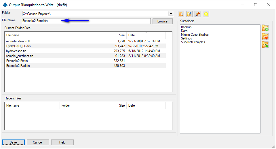
You are then prompted for the name of a triangulation (*.tin) to write. Specify the value as shown below and click the Save button when ready:
Prompting resumes:
Trim existing contours inside pad perimeter [Yes/<No>]? type N and press Enter
Contour the pad [<Yes>/No]? type N and press Enter
With the pad polyline completed, let's work on the pond.
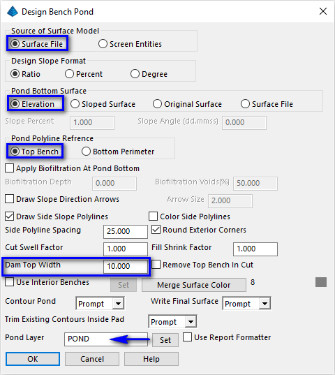
Set the values as shown above paying particular attention to the highlighted items and click OK when ready. When prompted:
Pick top of pond polyline: pick the rectangular pond polyline
A dialog box appears prompting for the Existing surface. Specify the surface model we just made as illustrated below and click Open when ready:
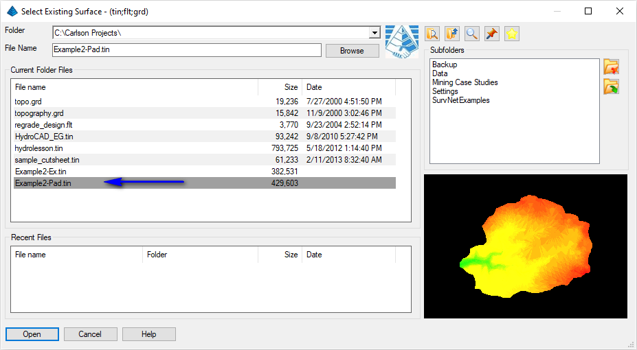
Prompting resumes:
Fill outslope ratio <3.000>: press Enter
Cut outslope ratio <3.000>: press Enter
Interior slope ratio <3.000>: press Enter
Range of existing elevations along dam top: 1991.51 to 2000.56 (your results may vary)
Top of bank elevation <1991.51>: type 1994 and press Enter
Pond bottom elevation: type 1986 and press Enter
Method to specify storage elevations [<Automatic>/Interval/Manual]? type A and press Enter
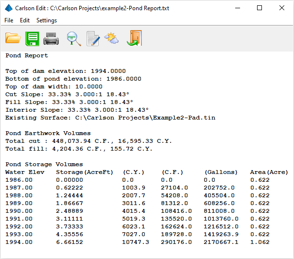
Slope projections from the source polyline are projected to the surface model file and preliminary results are displayed in the Standard Report Viewer similar to that shown below:
Review the report and notice the Cut Volume will be different from that of the Fill Volume. Click the Exit (Doorway) button to dismiss the report. Prompting resumes:
Adjust parameters and redesign pond [Yes/<No>]? type Y and press Enter
Balance cut/fill [Yes/<No>]? type Y and press Enter
Method to specify storage elevations [<Automatic>/Interval/Manual]? type A and press Enter
The solution is iterated until the balance tolerance is achieved and an updated report similar to that shown belows appears:
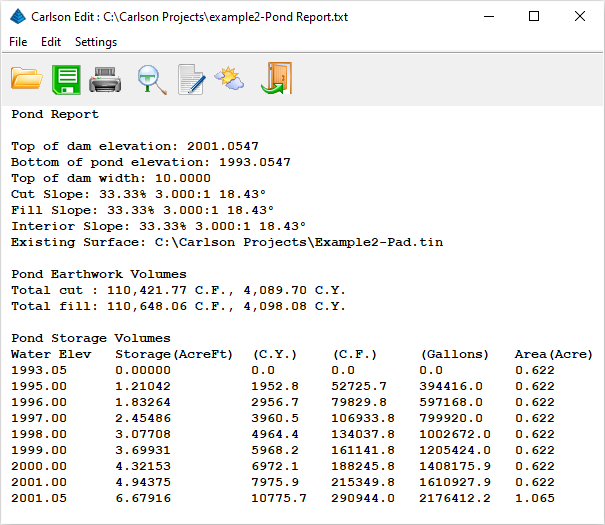
Let's accept the solution. Click the Exit (Doorway) button to dismiss the report. Prompting resumes:
Adjust parameters and redesign pond [Yes/<No>]? type N and press Enter
Write stage-storage file [Yes/<No>]? type N and press Enter
Write final surface to triangulation file [Yes/<No>]? type Y and press Enter
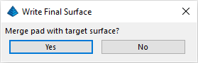
Merge pond with target surface [<Yes>/No]? type Y and press Enter
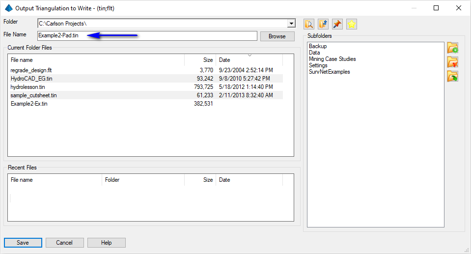
You are prompted for an output file. Specify the value as shown below and click the Save button when ready:
Prompting resumes:
Trim existing contours inside pad perimeter [Yes/<No>]? type Y and press Enter
Retain trimmed polyline segments [Yes/<No>]? type N and press Enter
Contour the pond [<Yes>/No]? type N and press Enter
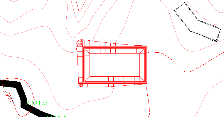
The result is a partial Fill, partial Cut Bench Pond as shown below:
 Set the values
as shown above paying particular attention to the highlighted
information and click OK when ready. When prompted
(using the illustration below as a guide):
Set the values
as shown above paying particular attention to the highlighted
information and click OK when ready. When prompted
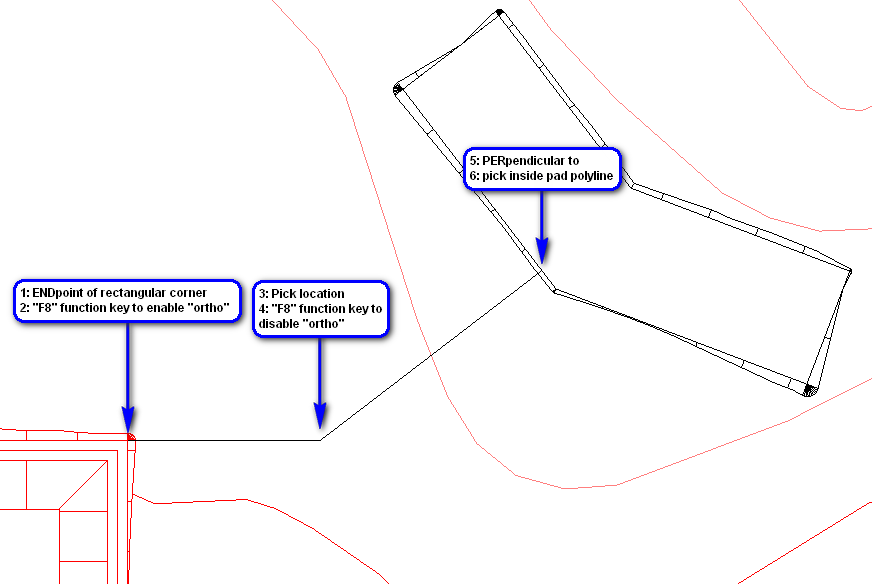
(using the illustration below as a guide):[Continue/Extend/Follow/Options/<Pick point or point numbers>]:type END and press Enter
Snap to END of: pick northeast rectangular corner of pond structure
[Arc/Close/Distance/Follow/Undo/<Pick point or point numbers>]: press F8 function key to enable "ortho" mode ('_ORTHOGONAL)
ORTHOMODE is currently off: [ON/OFf/Toggle]<Off>: _T
(ORTHOMODE is currently On):
[Arc/Close/Distance/Extend/Follow/Line/Undo/<Pick point or point numbers>]: pick the hinge location then press F8 function key to disable "ortho" mode
ORTHOMODE is currently on: [ON/OFf/Toggle]<On>: _T
(ORTHOMODE is currently Off): type PER and press Enter
Snap to PER of: pick inside pad polyline
Warning: last 3D polyline point at 0 elevation
[Arc/Close/Distance/Extend/Follow/Line/Undo/<Pick point or point numbers>]: press Enter
 This is an obvious
tool for creating design considerations. Our 3D polyline has one
problem... the hinge vertex may not have the elevation we desire.
Let's fix this.
This is an obvious
tool for creating design considerations. Our 3D polyline has one
problem... the hinge vertex may not have the elevation we desire.
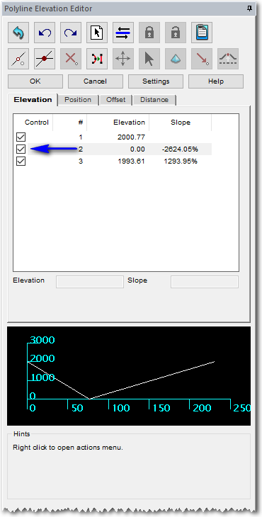
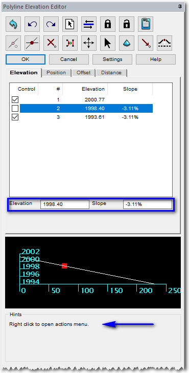
Let's fix this.NOTE: Bonus Tool! Issue the 3D Data -- Polyline Elevation Editor command. When prompted:
Select a polyline to edit: pick the polyline you just drew
A "docked" dialog box similar to that shown below appears:
| Before Edit | After Edit |
|---|---|
|
|
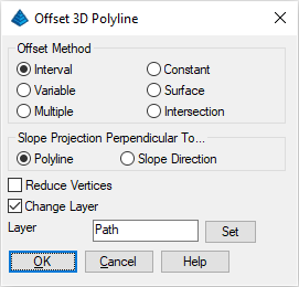
Set the values as shown above and click OK when ready. When prompted:
Percent/Ratio/<Horizontal offset amount>: type 10 and press Enter
Select/<Enter the common elevation <0.0000>>: press Enter
Select a polyline to offset: pick the polyline you just edited
Select side to offset [Both]: pick to the South of the polyline
Select a polyline to offset (Enter to end): press Enter
We now have a 3D-parallel offset of the initial polyline.
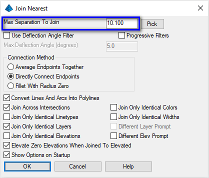
Note the Max Separation to Join value. Common practice is to pick the distance to span and then increase slightly to ensure the desired items will join. Set the values as shown above and click OK when ready. When prompted:
Select lines, arcs and unclosed polylines to join [Settings].
Select entities: pick the two polylines
Select entities: press Enter
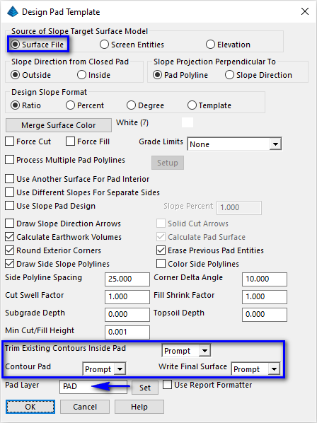
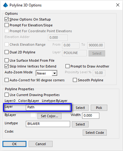
Now we have a 3D polyline closed perimeter, which can act as a pad. Re-issue the Surface -- Design Pad Template command to display a dialog box similar to that shown below:
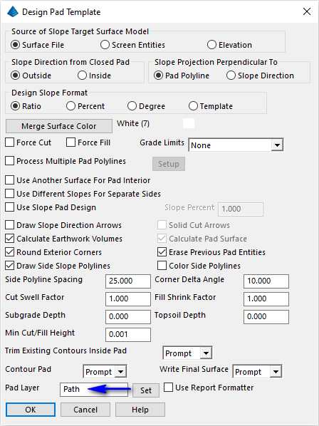
Set the values as shown above and click OK when ready. When prompted:
Pick pad polyline: pick the closed path polyline
Select Slope Target Surface (dialog): select the surface model recently created in the Bench Pond discussion and click Open
Fill outslope ratio <3.000>: press Enter
Cut outslope ratio <3.000>: type 5 and press Enter
Slope projections from the source polyline are projected to the surface model file and preliminary results are displayed. Review the report and click the Exit (Doorway) button to dismiss the report. Prompting resumes:
Adjust parameters and redesign pad [Yes/<No>]? type N and press Enter
Write Final Surface (dialog): click Create New Surface
Merge Final Surface (dialog): click Yes
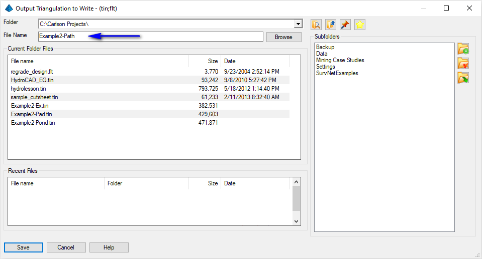
Write Triangulation Surface (dialog): set the value as shown below and click OK
Prompting resumes:
Trim existing contours inside pad perimeter [Yes/<No>]? type Y and press Enter
Retain trimmed polyline segments [Yes/<No>]? type N and press Enter
Contour the pad [<Yes>/No]? type N and press Enter
With the path completed, let's work on a new pond structure.
- To help distinguish from the Bench Pond we created earlier, create a new layer called POND2 and give it a color of Magenta and set it as the current layer. Dismiss the layer properties dialog box.
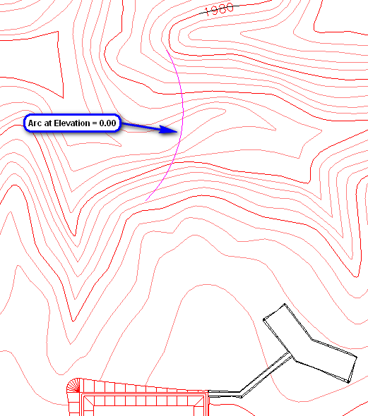
- Issue the Draw -- Arc -- 3 Point command and
when prompted:
Pick PC point or point numbers: pick a south end of the arc as shown below
Point on arc.
Pick point or point number: pick an interior arc point
PT point.
Pick point or point number: pick a north end of the arc as shown below
- Issue the Edit -- Polyline Utilities --
Entities to Polylines command. When prompted:
Select lines, arcs, circles, 3DFaces, ellipses, splines, multilines, regions and solids to convert.
[FILter]/<Select entities>: pick the arc you just drew and press Enter twice
Unlike Design Bench Pond, the Design Valley Pond routine requires only a polyline axis line for the center of the dam. The polyline can be a 2-point polyline, or it can have several vertices along its length to create a concave or convex dam structure. The main thing is to "overdraw" the axis polyline, make it ride up on the left and right hillside, well beyond the desired top of dam elevation. This allows the routine to look inward and find the extents of the dam on each hillside, without doing an artificial extension of the polyline. Just "overdo" the length of the axis line and you are in business.
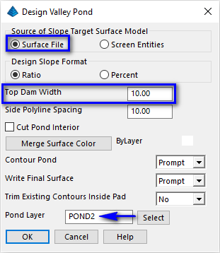
Our curved polyline runs from approximately 1976 on the south side of the valley to approximately 1976 on the north side. It crosses the valley at 1947. Let's decide to put the top of the dam at 1974 even. We will make the dam top 10' wide, with 4:1 downstream and 3:1 upstream slopes.
Issue the Surface -- Design Pond -- Design Valley Pond command. For this pond, use the starting values as shown below and click OK when ready:
When prompted:
Pick top of pond polyline: pick the polyline we just created
Select Existing Surface: specify the TIN file shown below and click the Open button when ready:

Pick point within pond: pick within the storage area (east of the arc polyline)
Outslope ratio <2.00>: type 4 and press Enter
Interior slope ratio <2.00>: type 3 and press Enter
Top of dam elevation: 1974
Calculate stage-storage values [<Yes>/No]? press Enter
Method to specify storage elevations [<Automatic>/Interval/Manual]? specify the Interval (i) method
Starting elevation <1947.68>: 1946 (your values may vary, we'll start just below the lowest elevation)
Elevation interval <2.00>: press Enter (review the report, click the Exit (doorway) button when ready)
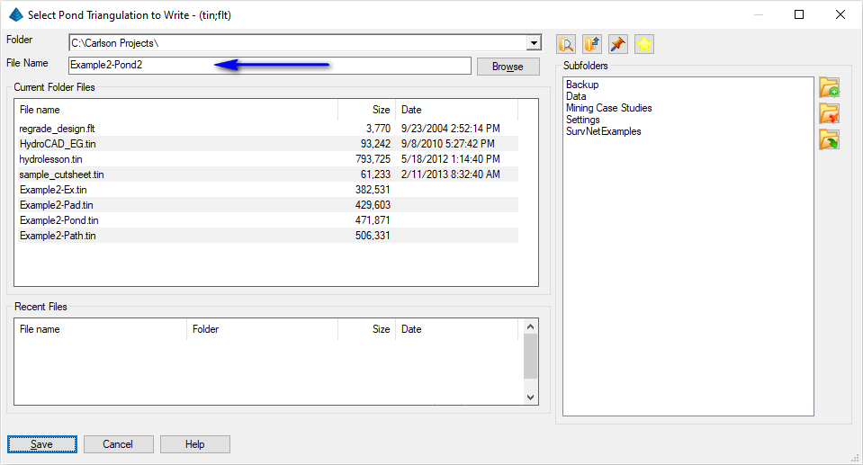
Output triangulation file of final pond surface [Yes/<No>]? indicate Yes
Output dam merged with existing or dam only [Merge/<Dam>]? indicate M and press Enter (indicate the file name below and click Save when ready)
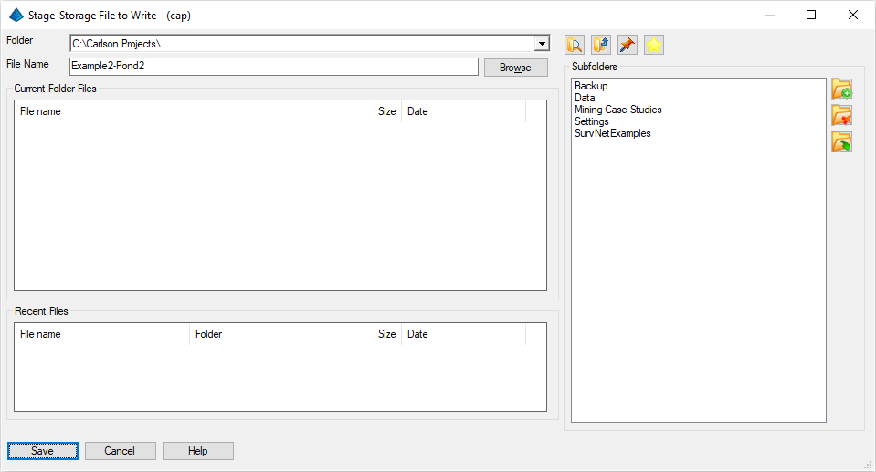
Write stage-storage file [Yes/<No>]? indicate Yes (indicate the file name below and click Save when ready)
Adjust parameters and redesign pond [Yes/<No>]? press Enter
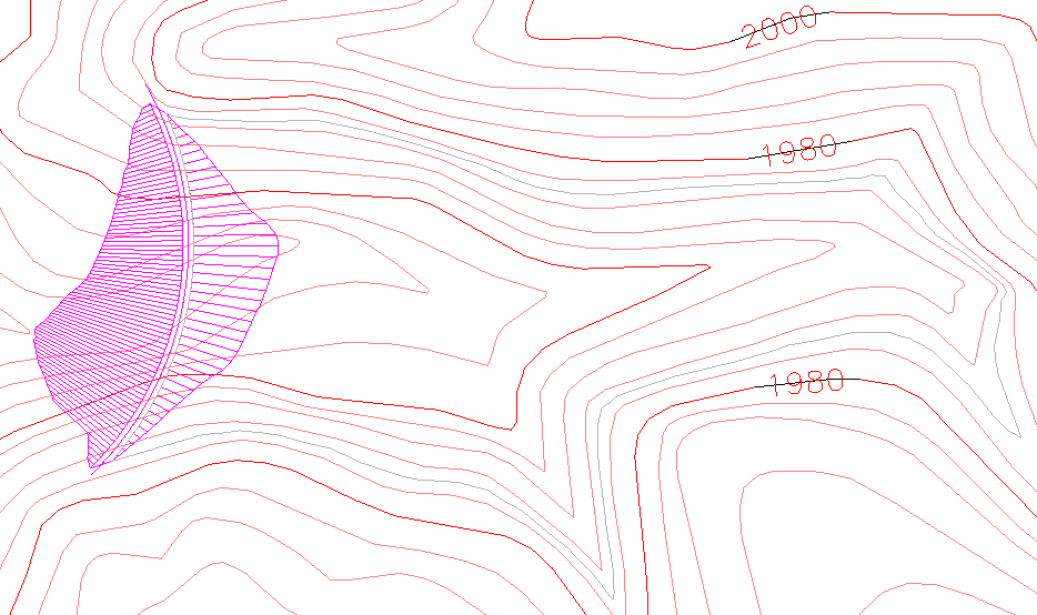
Contour the pond [<Yes>/No]? indicate No
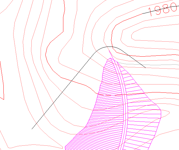
You should now have a pond that looks like the one in the following image:
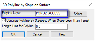
Set the values as shown above and click OK when ready. When prompted:
Choose Grid or Triangulation File (dialog): open the surface created in the previous step
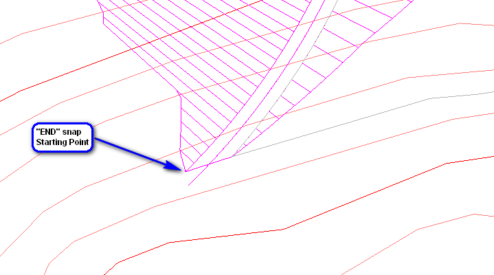
Pick origin point of 3D polyline: pick the starting location as shown below
Direction of 3D polyline [<Up>/Down]? type U and press Enter
Direction of 3D polyline facing up slope [<Left>/Right]? type R and press Enter
Slope format [<Percent>/Ratio/Degree]? press Enter
Enter design slope percent: type 6 and press Enter (a 3D polyline at the cited slope is drawn as illustrated below, your results will vary)
Adjust slope [Yes/<No>]? type N and press Enter
Pick origin point of 3D polyline (Enter to end): press Enter
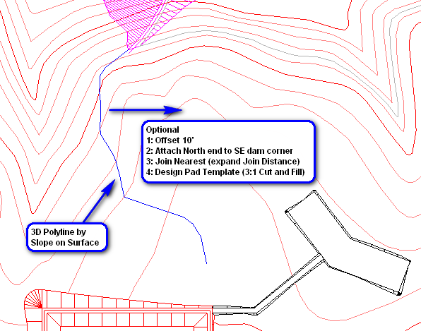
As optional exercises, construct the Haul surface through steps we've already discussed:
- Offset 3D Polyline (offset 10' to the East)
- Perform some minor clean-up (at the north end through the use of grips)
- Join Nearest (connect the two lines, an expanded Join Distance is warranted if the clean-up work above is performed)
- Design Pad Template (3:1 Cut and 3:1 Fill slopes, create a surface called Example2-Haul)
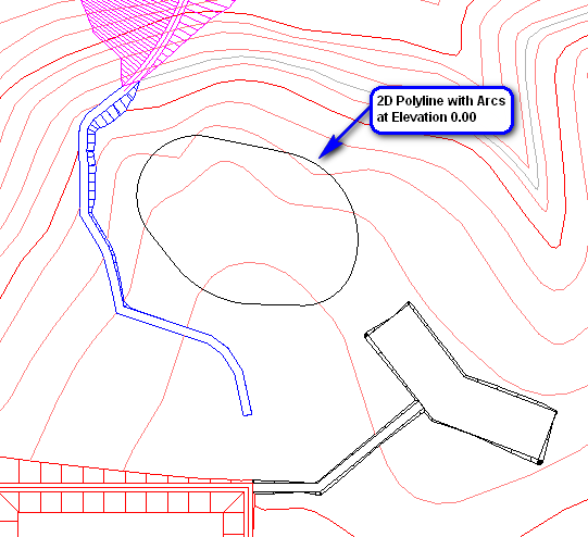 NOTE: For this type of shape, it is recommended
you use the standard CAD "polyline" (key-in pline)
with alternating combinations of:
NOTE: For this type of shape, it is recommended
you use the standard CAD "polyline" (key-in pline)
with alternating combinations of:
- line
- arc
- line
- follow
- arc
- line
- follow
- (etc repeating)
- close
Choose Grid or Tmesh File to Process (dialog): open the surface created in the previous step
Select polylines and lines to convert.
[FILter]/<Select entities>: pick the 2D polyline
[FILter]/<Select entities>: press Enter
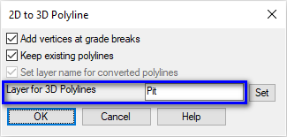
Set the values as shown above and click OK when ready. Re-run the Surface -- Design Pad Template command to display a dialog box similar to that shown below:
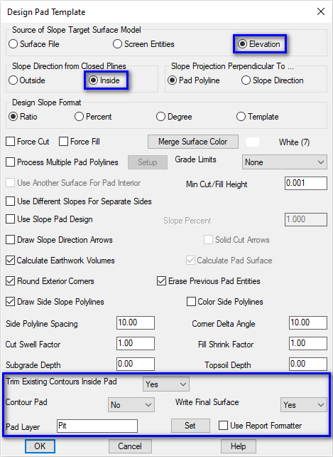
Set the values as shown above paying particular attention to the highlighted items and click OK when ready. When prompted:
Pick pad polyline: pick the 3D polyline just created
Fill outslope ratio <3.000>: press Enter
Cut outslope ratio <3.000>: press Enter
Target surface elevation: type 1976 and press Enter
Select Existing Surface for Volumes (Cancel for None) (dialog): open the surface created in the previous step
Review the Pad Report and click the Exit (Doorway) button when ready. Prompting resumes:
Adjust parameters and redesign pad [Yes/<No>]? press Enter
Output Triangulation to Write (dialog): set the value as shown below and click Save
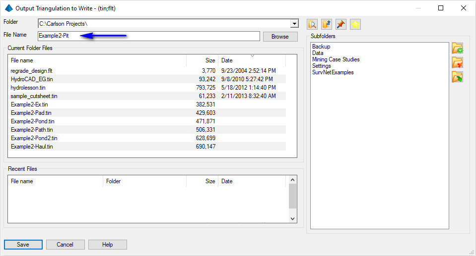
Prompting resumes:
Retain trimmed polyline segments [Yes/<No>]? type N and press Enter
Issue the View -- 3D View -- Surface File Viewer command to examine the results of the most recently created surface model thus far as illustrated below:
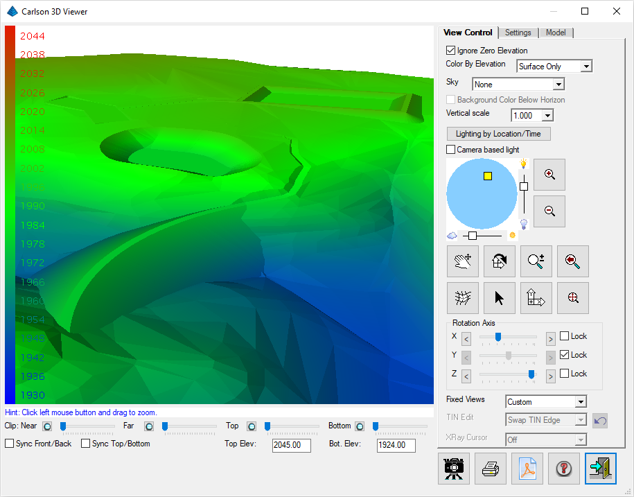
Click the Exit (Doorway) button when ready.
Let's create an existing ground ground profile from the TIN so that we can use this profile as a reference for the design profile to follow. Issue the Profiles -- Create Profile From -- Profile from Grid or Triangulation Surface command. When prompted:
Choose Grid or Triangulation File to Process (dialog): open the surface created in the previous step
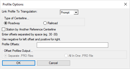
Profile Options (dialog): set the options as shown below and click OK
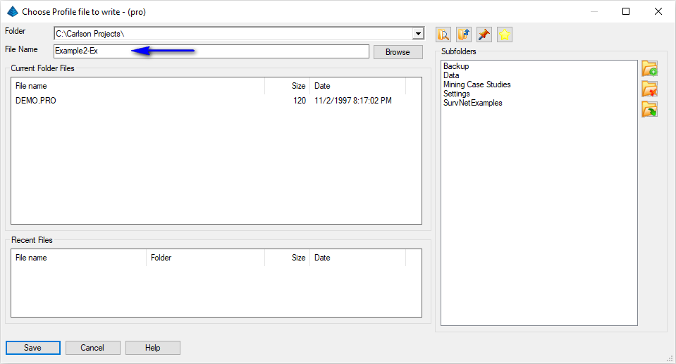
Choose Profile File to Write (dialog): set the options as shown below and click Save
Polyline should have been drawn in direction of increasing stations.
CL File/<Select centerline polyline>: pick the polyline you just drew
Starting station <0.0>: press Enter
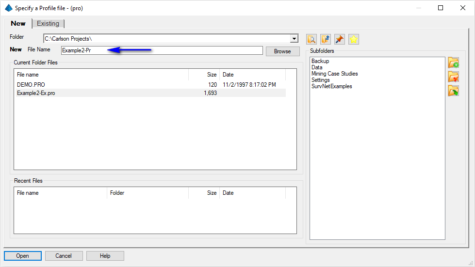
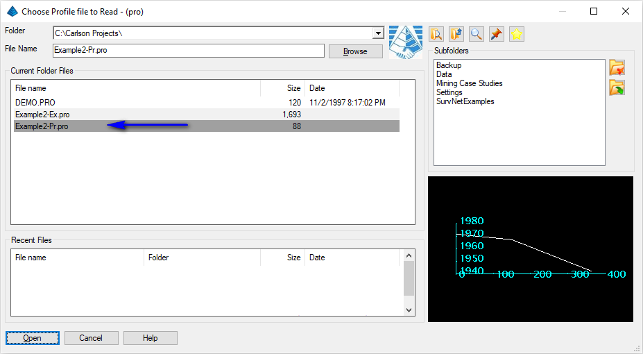
Issue the Profiles -- Profile Editor and when prompted, create the new file as illustrated below and click the Open button ready:
This displays a dialog box similar to that shown below:
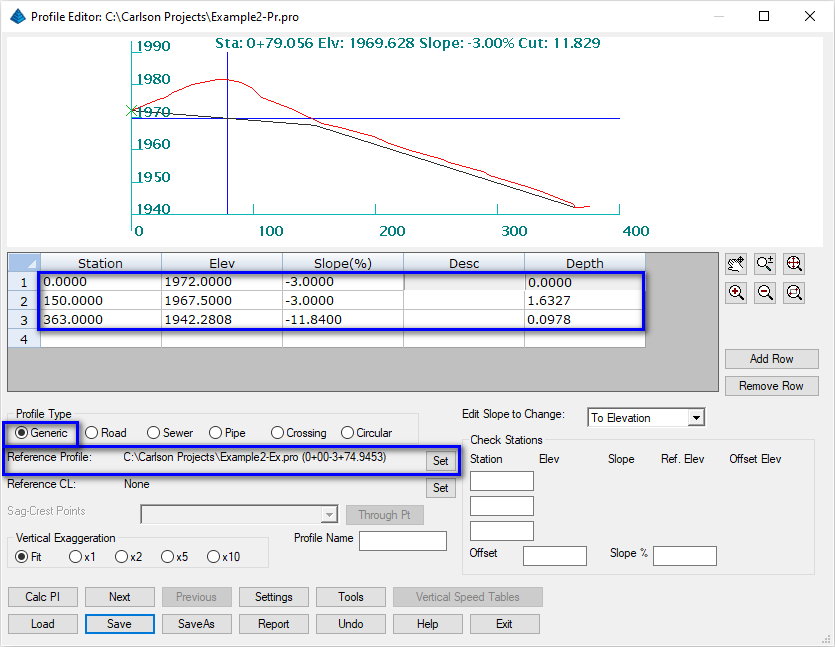
Within this dialog box, perform the following actions:
- Use the Set to set the Reference Profile of the existing ground profile you just created
- Specify a starting Station of 0 and give it a depth of 0
- Specify an ending Station of approximately that shown in the Reference Profile and give it a depth of 0
- Use the Add Row button to specify an internal vertical hinge point at a station of your choosing and a depth >= 0.75. With the elevation/grade calculated, adjust the grade for the first record to be the next even percent as illustrated above
- In all cases, make sure the new profile is always completely below existing ground so that the diversion ditch is always in cut
- Alternatively, end the profile at a station where desired so that any pond overflow is clear of the dam and simply flows over hill
- Save and exit from the Profile Editor when complete
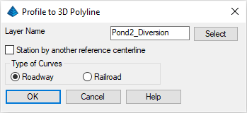
Set the values as shown above and click the OK button when ready. When prompted:
Polyline should have been drawn in direction of increasing stations.
CL File/<Select centerline polyline>: pick the 2D polyline we created earlier
Starting station <0.0>: press Enter
Select Profile to Read (dialog): select the design profile we created earlier and click Open
Erase centerline [Yes/<No>]? type Y and press Enter
The result is a 3D polyline along the length of the 2D polyline but at elevations defined by the design profile.
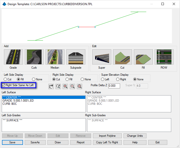
We'll focus on this horizontal strip of icon options:
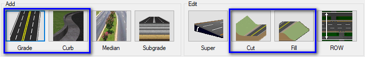
- To begin, click on the Grade button to display
a dialog box similar to that shown shown below:
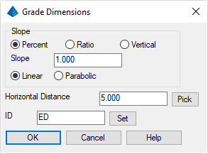
Set the values as shown above to ultimately create a 10' wide surface that drains to the center at a 1% slope and terminates with an ID of ED (edge drainage). Click OK when ready. - Click on the Curb button to display a dialog
box similar to that shown shown below:
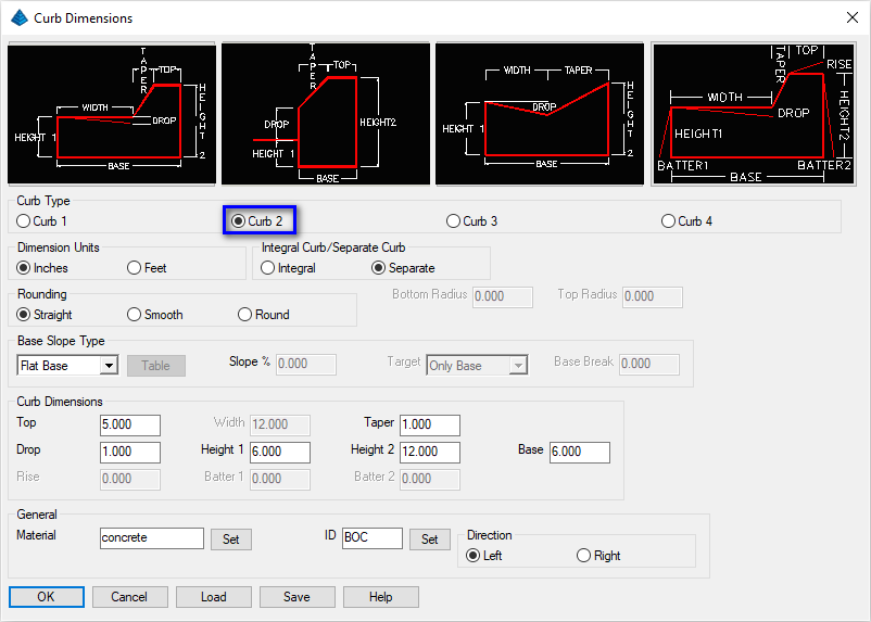
Set the values as shown above to ultimately create a simple concrete curb with an ID of BOC (back of curb). Click OK when ready. - Click on the Cut button to display a dialog
box similar to that shown shown below:
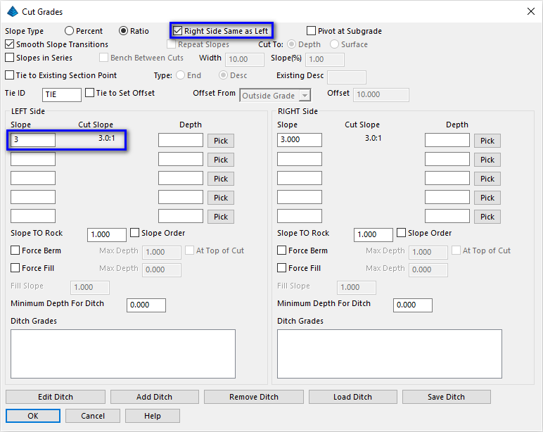
Set the values as shown above to ultimately create a single catch-slope used on both sides of the template for Cut scenarios with an ID of TIE (tie point). Click OK when ready. - Click on the Fill button to display a dialog
box similar to that shown shown below:
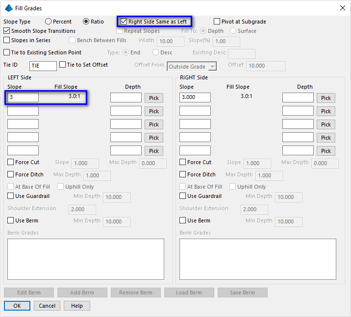
Set the values as shown above to ultimately create a single catch-slope used on both sides of the template for Fill scenarios with an ID of TIE (tie point). Click OK when ready.
Verify the completed template resembles that shown below (paying attention to the highlighted item) and click Save and Exit when ready:
Now let's use the Surface -- Design Pad Template routine one more time as illustrated below:
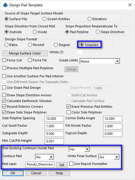
For the first time, we have selected the Template option as illustrated above. Set the values as shown above paying particular attention to the highlighted items and click OK when ready. When prompted:
Pick pad polyline: pick the 3D polyline created earlier
Select Slope Target Surface (dialog): open the most recent surface for the project
Select Template (dialog): pick the template file created earlier
Review the Pad Report and click the Exit (Doorway) button when ready. Prompting resumes:
Merge Final Surface (dialog): click Yes
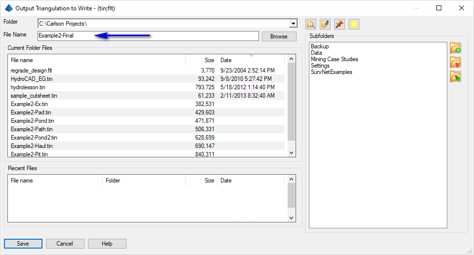
Output Triangulation to Write (dialog): set the value as shown below and click Save
Prompting resumes:
Retain trimmed polyline segments [Yes/<No>]? type N and press Enter
Issue the View -- 3D View -- Surface File Viewer command to examine the results as illustrated below:
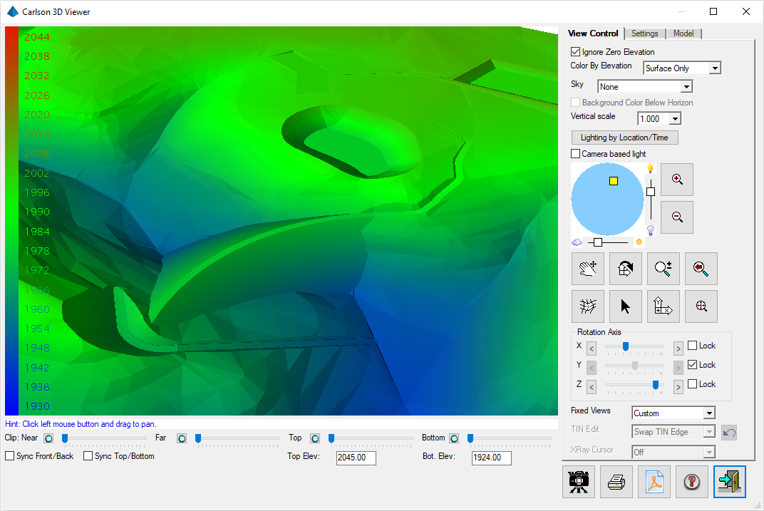
Click the Exit (Doorway) button when ready.
Finally, let's see how much earthwork has been moved since we started. Issue the Surface -- Volumes by Triangulation -- Two Triangulation Surface Volumes command. When prompted:
Select EXISTING Surface Triangulation File (dialog): open the first surface model created in this project
Select FINAL Surface Triangulation File (dialog): open the last surface for the project
Volume Report Options (dialog): accept the default values
Select Inclusion polylines or press Enter for none.
[FILter]/<Select entities<: press Enter
Select Exclusion polylines or press Enter for none.
[FILter]/<Select entities<: press Enter
Review the results as illustrated below (your results will be different):
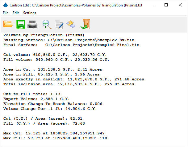
Click the Exit (Doorway) button when ready.