3D Polyline
This command creates a 3D Polyline. A 3D Polyline is a version
of a polyline that
can have different elevation at every vertex. 3D Polylines can not
have arcs and the program will instead draw a series of short
chords to closely follow an arc.
The 3D Polyline command is
available from the Draw
pulldown menu, from the Draw toolbar or at the Command: line
(3DP). Unless disabled, the
Polyline 3D Options dialog
box will appear after starting Carlson's 3D Polyline command.
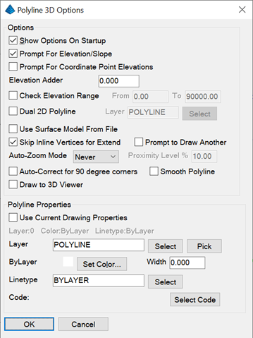
Show Options on Startup:
When this option is enabled, the Polyline 3D Options dialog box will
display automatically upon starting the 3D Polyline command. If disabled, you
can still get to this dialog by typing O for Options at the command
prompt.
Prompt for Elevation/Slope:
When this option is enabled, the elevation for each new vertex will
be displayed as a prompt, giving you an opportunity to override
that value by typing in a new elevation. When disabled, the
elevation to be assigned to each new vertex is displayed but you
are not given a chance to assign a different elevation.
Prompt for Coordinate Point
Elevations: This option only applies if you specify a point
number from an associated Coordinate (.CRD) file to establish the
X,Y,Z values for a new 3D Polyline vertex. When this option is
enabled, the elevation for each new vertex will be displayed as a
prompt, giving you an opportunity to override that value by typing
in a new elevation. When disabled, the elevation to be assigned to
each new vertex is displayed but you are not given a chance to
assign a different elevation.
Elevation Adder: Use this
setting to add a constant elevation value to all default elevation
values.
Check Elevation Range:
Enabling this option allows you to monitor elevations assigned to
3D Polyline vertices and issue a warning (with options to correct)
if the elevation falls outside the specified range. If the proposed
elevation of a 3D Polyline vertex falls outside the range
specified, the Warning: Elevation
Range dialog box is displayed. The Warning: Elevation Range dialog box
allows you to assign a new elevation to the vertex, adjust the
acceptable range of elevations or turn OFF monitoring of
elevations. 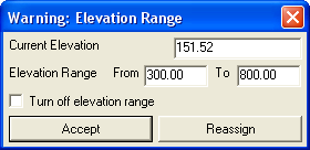 Dual 2D Polyline: This option creates
a 2D polyline in addition to the 3D polyline. The 2D polyline is
drawn on a separate layer, uses elevation zero and has true arcs
instead of the series chord segments used for arcs in 3D
polylines.
Dual 2D Polyline: This option creates
a 2D polyline in addition to the 3D polyline. The 2D polyline is
drawn on a separate layer, uses elevation zero and has true arcs
instead of the series chord segments used for arcs in 3D
polylines.
Use Surface Model From File: Selecting this option allows
you to use a Surface Model (.TIN, .GRD, .FLT) file to determine the
elevation for each new 3D Polyline vertex.
Skip Inline Vertices for Extend: This
setting applies to the "Extend" option with the Total Distance SubMenu option. If enabled, an
existing vertex will dissolve when lengthening a 3D Polyline
segment.
Prompt To Draw Another: This option stays in the command
after completing the polyline and prompts whether you want to draw
another polyline.
Auto-Zoom Mode: This
setting provides 3 options for Auto-Zoom: Never, Proximity or
Always. The "Never" setting requires you to manually Zoom or Pan to
keep the current polyline vertex centered in the drawing screen.
The "Proximity" setting will activate the "Proximity Level" setting
and will automatically re-center the view only if the current
polyline vertex is within a certain distance of the limits of the
drawing area. The "Always" option will automatically re-center the
view after each new polyline vertex is added.
In the "Polyline Properties" section of the dialog box you have
several alternatives for specifying the layer, color and linetype
of the newly created polyline.
Auto-Correct For 90 Degree Corners: This option will adjust
two line segments to make an exact 90 degree corner when the
original lines are nearly 90 degrees.
Smooth Polyline: This option applies for drawing smooth
polylines such as a path for a stream. The Bezier smoothing method
is used which passes through all the points and smooths only
between the points.
Draw to 3D Viewer: When the 3D Viewer is running during Draw
3D Polyline, then this option will draw the 3D polyline
simultaneously in the 3D Viewer and the drawing. This is a way to
see the 3D polyline is a 3D scene with other objects while entering
the 3D polyline data.
Use Current Drawing
Properties: Select this option if you want the layer, color
and linetype of the newly created polyline to match those currently
set in the drawing.
Layer: Use this setting to
manually assign the layer for the newly created polyline. You can
type in the new layer name, use the "Select" button to choose an
existing layer from the drawing's layer list or use the "Pick"
button to select an entity in the drawing and match its layer.
Set Color: Use this button
to manually specify a color for the newly created polyline.
Width: Specify the width of
the newly created polyline.
Linetype: Use the "Select"
button to manually specify a linetype for the newly created
polyline.
Select Code: This option
allows you to set the layer, color and linetype of a new polyline
by using the properties assigned to a Field to Finish field code.
The field code is selected from an existing Field Code table (.FLD)
file that has been previously specified in the Point Defaults dialog box.
Prompts
For A 3D Polyline With A Specified Elevation At Each Vertex:
Command: 3dp
[Continue/Extend/Follow/Options/<Pick point or point
numbers>]: screen pick a point
Interpolate/Object/<Elevation> <0.00>:
150.50
Z: 150.50
[Arc/Close/Distance/Follow/Undo/<Pick point or point
numbers>]: screen pick a point
Percent/Ratio/Elevation/Degree/Object/Osnap[.]/Next point
or elevation<Interpolate>: 155.25
Z: 155.25, Hz dist: 324.63, Slope dist: 324.66, Slope: 1.5%
Ratio: 68.3:1
[Arc/Close/Distance/Extend/Follow/Line/Undo/<Pick point
or point numbers>]: screen pick a point
Percent/Ratio/Elevation/Degree/Object/Osnap[.]/Next point
or elevation<Interpolate>: 148.12
Z: 148.12, Hz dist: 272.88, Slope dist: 272.98, Slope:
-2.6% Ratio: -38.3:1
[Arc/Close/Distance/Extend/Follow/Line/Undo/<Pick point
or point numbers>]: press Enter
Command:
For A 3D Polyline With Interpolated Elevations At One or More
Vertices:
Command:3dp
[Continue/Extend/Follow/Options/<Pick point or point
numbers>]: screen pick a point
Interpolate/Object/<Elevation> <0.00>:
91.73
Z: 91.73
[Arc/Close/Distance/Follow/Undo/<Pick point or point
numbers>]: screen pick a point
Percent/Ratio/Elevation/Degree/Object/Osnap[.]/Next point
or elevation<Interpolate>: screen pick a
point
This point elevation will be interpolated upon
completion.
Percent/Ratio/Elevation/Degree/Object/Osnap[.]/Next point
or elevation<Interpolate>: screen pick a
point
This point elevation will be interpolated upon
completion.
Percent/Ratio/Elevation/Degree/Object/Osnap[.]/Next point
or elevation<Interpolate>: screen pick a
point
This point elevation will be interpolated upon
completion.
Percent/Ratio/Elevation/Degree/Object/Osnap[.]/Next point
or elevation<Interpolate>: 94.44
Z: 94.44, Hz dist: 79.39, Slope dist: 122.88, Slope: 0.8%
Ratio: 122.4:1
[Arc/Close/Distance/Extend/Follow/Line/Undo/<Pick point
or point numbers>]: press Enter
Command:
Note that the difference between this and the previous example is
that, instead of entering an elevation for each vertex, we are
screen picking another new vertex. Each time we neglect to enter an
elevation we are notified that, "This point elevation will be
interpolated upon completion." After we specify "94.44" as the
elevation of the last vertex, the slope of the interpolated
segments is calculated using the total elevation change and the
total length of all interpolated segments. Now, the elevations of
all vertices can be determined and set based on the resulting
slope.
Options and SubMenu Options
Once all settings have been specified and the "OK" button is
picked, the options shown below are available from the Command:
line. To issue any of these options, simply type in the capitalized
portion of the Option at the Command: line and press Enter. The
default option is always shown between angle brackets <
Default >.
When starting a new 3D Polyline, the initial set of options assist
you in setting the X,Y location of the first vertex:
Continue: This option
allows you to select an existing polyline to which you'd like to
add more line or arc segments. When prompted to "Select a polyline
to continue or extend:", you may pick anywhere on the existing
polyline and the new segment will begin at the ending vertex
nearest your cursor. New line or arc segments can be added by
screen-picking or using the options at the Command: line. Once
finished adding segments, they are automatically joined to the
original polyline.
Extend: This option gives
you many ways to lengthen or shorten an existing polyline using the
abbreviated SubMenu options shown below. Some of these options
create additional segments at the end of the existing polyline and
some allow you to change the length of the ending segment of the
polyline. When prompted to "Select a polyline to continue or
extend:", you may pick anywhere on the existing polyline and the
"Extend" will occur at the ending vertex nearest your cursor. Once
finished Extending, the new segments are automatically joined to
the original polyline.
[I / R / L / S / T / A / B / E / U / X / Help / <Enter
or Pick Distance>]
I - Input mode - This option toggles the
distance input between feet & inches (will prompt first for
feet, then prompt again for inches) and decimal feet.
R - Right rotate - From the ending
vertex, turns the pointer 90-degrees to the right and then prompts
for a distance.
L - Left rotate - From the ending vertex,
turns the pointer 90-degrees to the left and then prompts for a
distance.
S - Switch direction - From the ending
vertex, turns the pointer 180-degrees and then prompts for a
distance.
T - Total
distance - Prompts you to "Enter total distance
(100.00)" and displays the current length of the segment in
parentheses. If a number smaller than the current distance is
entered, this option will shorten the existing segment. If a number
larger than the current distance is entered, this option will
lengthen the existing segment. This option is also affected by the
Skip Inline Vertices for Extend setting
in the Polyline 3D Options
dialog box. If "Skip Inline Vertices for Extend" is enabled, then
the existing vertex will be dissolved when lengthening a segment.
If the setting is not enabled, then the existing vertex will be
left intact and an additional segment will be created inline.
A - Angle change - From the ending
vertex, prompts you to "Enter Angle (ddd.mmss):" to turn the
pointer by a specified angle and then prompts for a distance.
B - Bearing/Azimuth/Turned/Deflection -
From the ending vertex, this option allows you to set the pointer
direction by specifying an Angle. The Angle format is Qdd.mmss and
there are a variety of ways to use the "Q" value to specify the
Angle. See here for more.
E - Extend to edge - Extends current
segment to another line or entity
U - Undo - Undo last action
X - Quit extend mode - Returns to normal
3D Polyline Draw mode
Help - Displays the descriptions of the
Extend options
Enter or Pick Distance - Distance to
extend the current segment
Follow: This option allows
you to trace all or a portion of an existing polyline. After
issuing the "Follow" option, you are prompted to "Select the
polyline to Follow:" and then to "Specify the first follow point:".
After snapping to a starting point on the polyline, you are asked
whether you want to "Interpolate follow vertices elevations?".
After answering Yes or No, you will then be prompted to specify the
"Last follow point or follow distance:" where you can snap to
another point on the polyline or type in a distance to trace the
existing polyline.
Options: This will display
the Polyline 3D Options
dialog box.
Pick Point or Point
Numbers: This is the default prompt for the command. From
here you can set a new polyline vertex by screen picking, entering
coordinates in X,Y format or entering a point number from the
associated Coordinate (.CRD) file.
After setting its location, the next set of options help you
calculate the elevation of the initial vertex:
Interpolate: This option
will set the elevation of the vertex by calculating the slope
between other vertices of known elevation.
Object: This option allows
you to "Select an elevation label or a point on a polyline:" to set
the elevation of the vertex. Elevation labels such as "FFE: 124.85"
or "Z: 124.85" can be selected.
Adjust: This option allows you to add or subtract an amount
from the elevation like for a curb offset.
Elevation: This is the
default option and prompts you to type in the elevation for the
vertex.
For subsequent 3D Polyline vertices, several options are added to
assist you in setting the X,Y location of each new vertex:
Arc/Line: New polyline
segments can be either an Arc or a Line segment. If the last
polyline segment drawn was a LINE, then the "Arc" option will be
shown as an available option; however, if the last polyline segment
drawn was an ARC, then the "Line" option will be available.
When in the "Arc" mode, there are many additional SubMenu options
available to you for creating an arc segment within the new
polyline. The options are generated directly from the standard CAD
version of the PLINE command and include Radius Point, Radius
Length, Arc Length, Chord and Second Point (Point on Curve).
Close: This option will
create a new Line or Arc segment back to the starting vertex of the
polyline and results in a closed polyline.
Distance: This option
allows you to first enter a distance for the new Line segment and
then to specify the direction using one of three methods: Cursor,
Line or Angle.
Cursor - This method will draw the
polyline segment in the direction of your cursor position.
Line - This method prompts you to select
a line or polyline segment to which it will draw a parallel
segment.
Angle - This method prompts you for an
Angle to determine the direction of your new polyline segment. The
Angle format is Qdd.mmss and there are a variety of ways to use the
"Q" value to specify the Angle. See here for
more.
Undo: Undo the last drawn
polyline segment.
After setting subsequent vertices, several more options are added
to help you calculate the elevation of each new vertex:
Percent: This option allows
you to specify the slope in Percent format (3%) from the previous
vertex.
Ratio: This option allows
you to specify the slope in Ratio format (for 3:1, enter 3) from
the previous vertex.
Degree: This option allows
you to specify the slope angle in decimal degree format (dd.dddd)
from the previous vertex.
Osnap[.]: Using the [.]
will toggle Running OSNAP settings ON or OFF.
Angle Entry
Methods
The Angle format is Qdd.mmss where: Q=quadrant/angle, d=degrees,
m=minutes and s=seconds.
The Quadrant/Angle can be specified as:
1=NE (NorthEast)
2=SE (SouthEast)
3=SW (SouthWest)
4=NW (NorthWest)
5=AZ (AZimuth)
6=AL (turned Angle-Left)
7=AR (turned Angle-Right)
8=DL (Deflection angle-Left)
9=DR (Deflection angle-Right)
Pulldown Menu Location: Draw
Keyboard Command: 3DP
Prerequisite: None