- If you get the Start Page, pick Open Files.
- If you get the Startup Wizard dialog box, click the Browse button.
- If you are taken directly into CAD, click File -- Open.
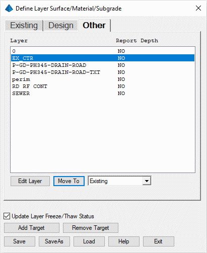
Use the table below along with the Move To button to assign the layers cited below to their desired target:
| Existing | Design | Other |
|---|---|---|
| EX_CTR | RD RF CONT | 0 |
| P-GD-PH345-DRAIN-ROAD | ||
| perim | ||
| SEWER |
Select boundary polylines.
[FILter]/<Select entities>: pick the perimeter polyline
This selected polyline is now set as the boundary polyline for the rest of this tutorial.
- To make the Existing Ground surface, issue the Takeoff -- Make Existing Ground Surface.
- To make the Design Ground surface, issue the Takeoff -- Make Design Surface.
- name
- location (x,y)
- rim elevation
- invert-in
- invert-out
- Input Trench From Polyline is used when the drawing contains polylines for the trench lines and labels with the trench data.
- Create Trench Network Structure lets you pick the structure locations and enter the data in a dialog.
Issue the Trench -- Input Trench Line command to display the dialog box below:
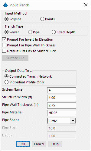
With the data available to us, set the values as shown in the dialog box and click OK when ready. For each point in the trench polyline, the program zooms the drawing to that point. The trench data can be picked from labels in the drawing:
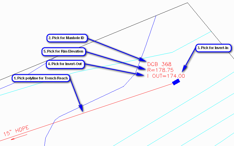
When prompted:
Pick a polyline that represents a trench reach: pick the pipe polyline
Starting Station of trench reach <0.0>: press Enter
Select/<Enter Manhole ID>: type s and press Enter
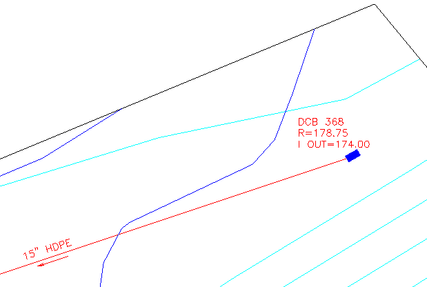
Enter/<Select text of Manhole ID>: pick the DCB 368 label
Undo/Select/Interpolate/<Enter Invert-in Elevation <0.0000>>: type s and press Enter
Undo/Enter/Interpolate/<Select text of Invert-in elevation>: pick the I Out=174.00 label (since this is the upstream starting manhole, there really isn't a separate invert-in so we are using the invert-out)
Undo/Select/<Enter Invert-out Elevation <0.0000>>: type s and press Enter
Undo/Enter/<Select text of Invert-out elevation>: pick the I Out=174.00 label
Undo/None/Select/<Enter manhole rim elevation <0.0000>>: type s and press Enter
Undo/None/Enter/<Select text of manhole rim elevation>: pick the R=178.75 label
Enter/<Select text of Manhole ID> [DCB 369]: pick the DCB 367 label
Undo/Enter/Interpolate/<Select text of Invert-in elevation>: pick the I In=172.85 label
Undo/Enter/<Select text of Invert-out elevation>: pick the I Out=172.35 label
Undo/None/Enter/<Select text of manhole rim elevation>: pick the R=178.50 label
Undo/Select/Group/<Enter Pipe Size in <0.0000>>: type s and press Enter
Undo/Enter/Group/<Select text of pipe size>: pick the 15" HDPE label
Enter/<Select text of Manhole ID> [DCB 368]: pick the CB 347 label
Undo/Enter/Interpolate/<Select text of Invert-in elevation>: pick the I In=170.54 (CB 367) label
Undo/Enter/<Select text of Invert-out elevation>: pick the I Out=166.10 label
Undo/None/Enter/<Select text of manhole rim elevation>: pick the R=176.50 label
Undo/Enter/Group/<Select text of pipe size>: pick the 15" HDPE label
Another Trench Line [<Yes>/No]? type n and press Enter
That completes this trench run and Takeoff/Trench draws its own trench polyline and labels.
NOTE: If the drawing doesn't have labels for the data, then you can enter the values.
Next, run the Trench -- Create Trench Network Structure command. When prompted:
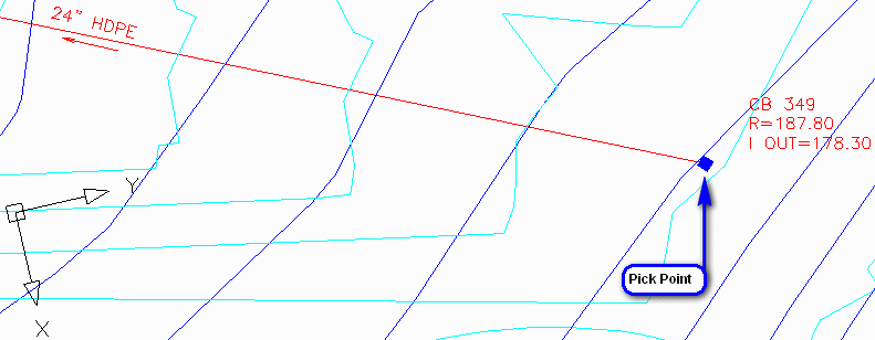
Locate by pick point, point number or station-offset [<Pick>/Number/CL]? press Enter for the Pick option
Pick structure location: pick the pipe polyline near the CB 349 end-point
A dialog box similar to that shown below appears:
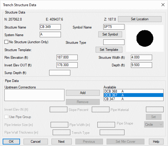
Set the values as shown and click OK when ready. Prompting resumes:
Pick structure location (Enter to end): press Enter
Since the downstream location for this reach has already been created from the Input Trench Line exercise, we don't need to create it again. Use Zoom and/or Pan functionality to center the display in the CB 347 area. Initiate the Trench -- Edit Trench Network Structure command. When prompted:
Select sewer structure to edit: pick either the symbol for CB 347 or its recently created label
A dialog box similar to that shown below appears:
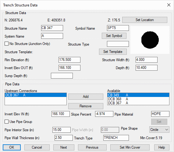
Since this is the downstream terminus for the network, highlight/select the CB 349 structure and click the Add button. Fill the values as shown above. When complete and as needed, highlight/select the DCB 367 structure and click the Add button. Fill the values as shown below:
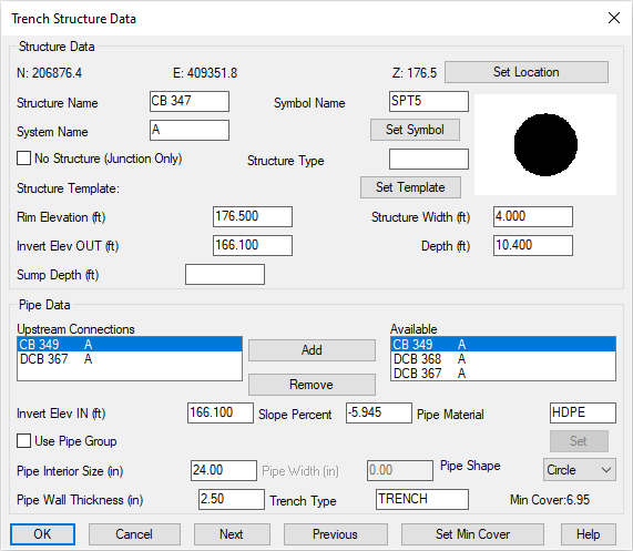
When complete, click the OK button. This creates a link from CB 347 to its upstream location(s).
NOTE: It is also possible to directly edit the structure data by using double-click functionality on the Trench-placed structure or its label.
The primary dialog box appears, similar to that shown below:
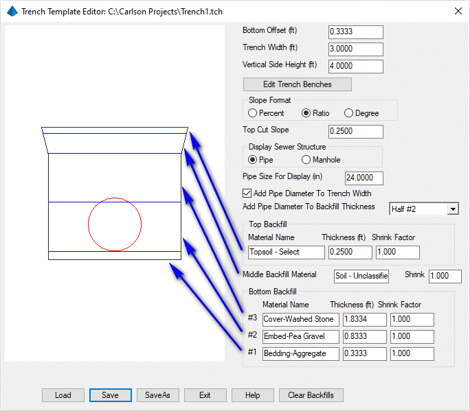
Supply the values as illustrated below (or design your own!). In the above example, we are:
- assuming the in-situ material is of suitable composition (e.g. not "fatty clays", peat moss, etc),
- using 4" of crushed aggregate, granite, etc, for the bedding material,
- placing the pipe directly on top of the bedding material,
- using 10" of pea gravel, for the embedment material (this thickness will vary by ½ of the pipe diameter),
- using 22" of washed stone, for the cover material,
- using a variable thickness of unclassified, excavated material to fill in the remainder of the trench (except the final 3"), and,
- using 3" of select topsoil to complete the backfill.
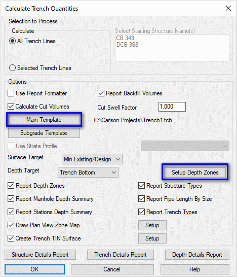
Set the values shown above making particular note of:
- Specifying the Main Template trench configuration we just created, and,
- Setting the Surface Target to Min Existing/Design (permitting quick excavation of the site to the lower of Existing vs. Design elevation before trenching commences), and,
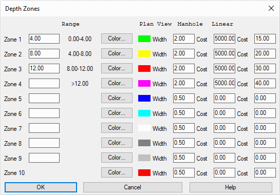
- Setting the Setup Depth Zones to the values as shown in the dialog box below (click OK when complete)
Finally, click OK in the main dialog and the report similar to that shown below is displayed:
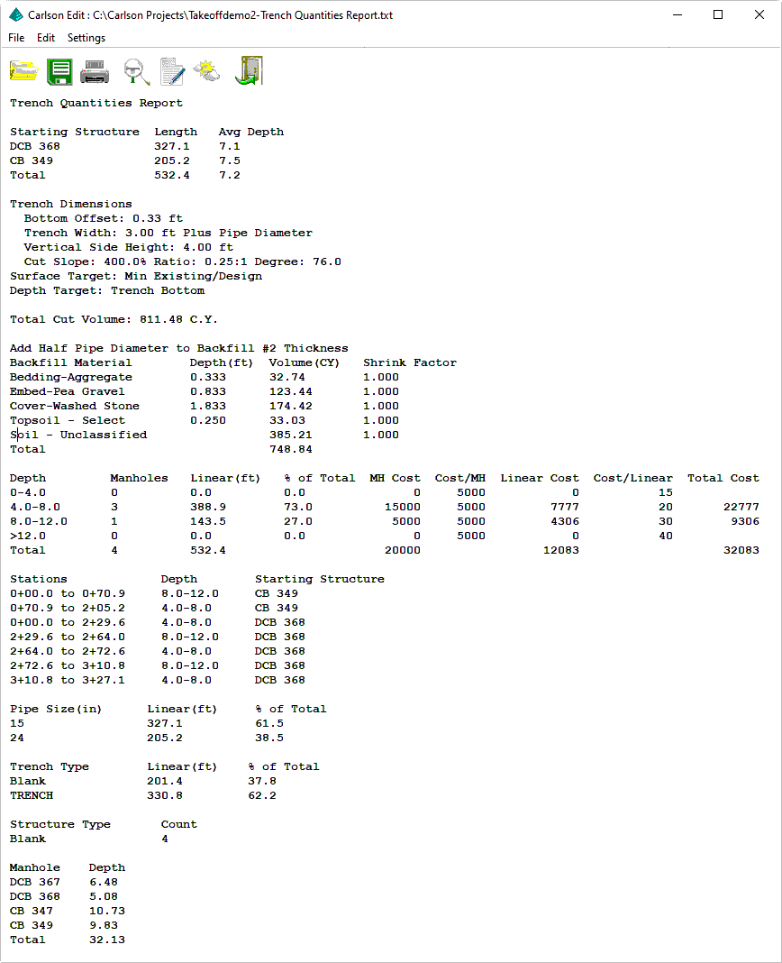
Review the report and click the Exit (doorway) button when ready. When prompted:
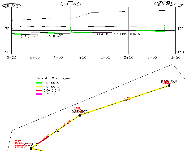
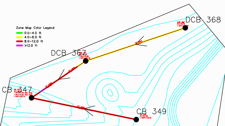
Draw zone map color legend on the screen [Yes/<No>]? type y and press Enter
Pick a point for color legend: pick a location toward the upper left of the project site
Legend size <4.00>: press Enter
The depth zones in the plan view with Zone Map Color Legend are shown similar to that below (certain layers have been frozen for clarity):
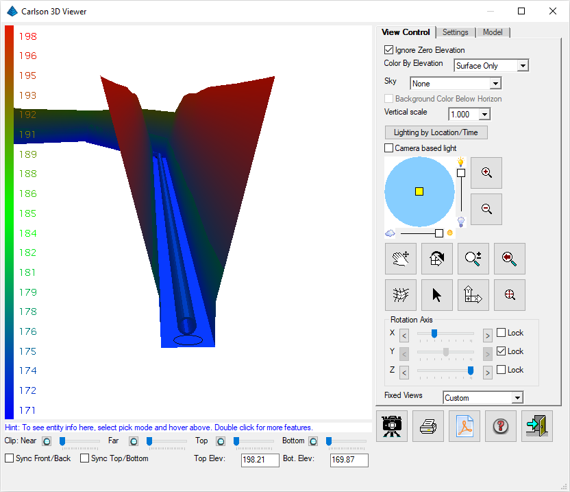
Finally, use the Display -- 3D Viewer Window and window around the 3D faces to view the trench in 3D as illustrated below:
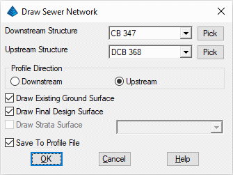
When prompted:
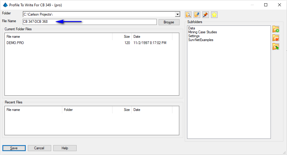
Supply the profile name as cited above and click Save when ready. Next, the Draw Profile dialog appears as illustrated below:
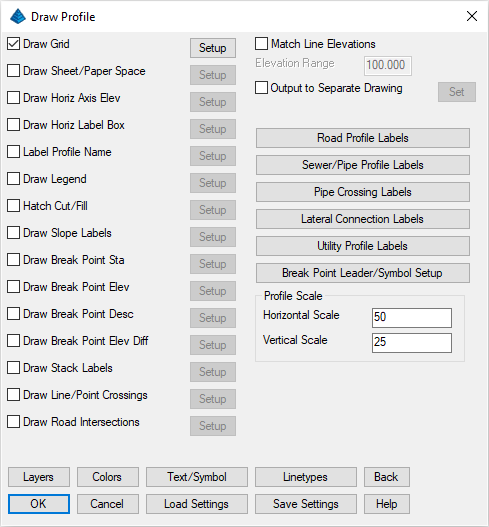
We'd like to fine-tune the content of the forthcoming annotation. Click the Sewer/Pipe Profile Labels button and navigate to the Pipe tab as illustrated below:
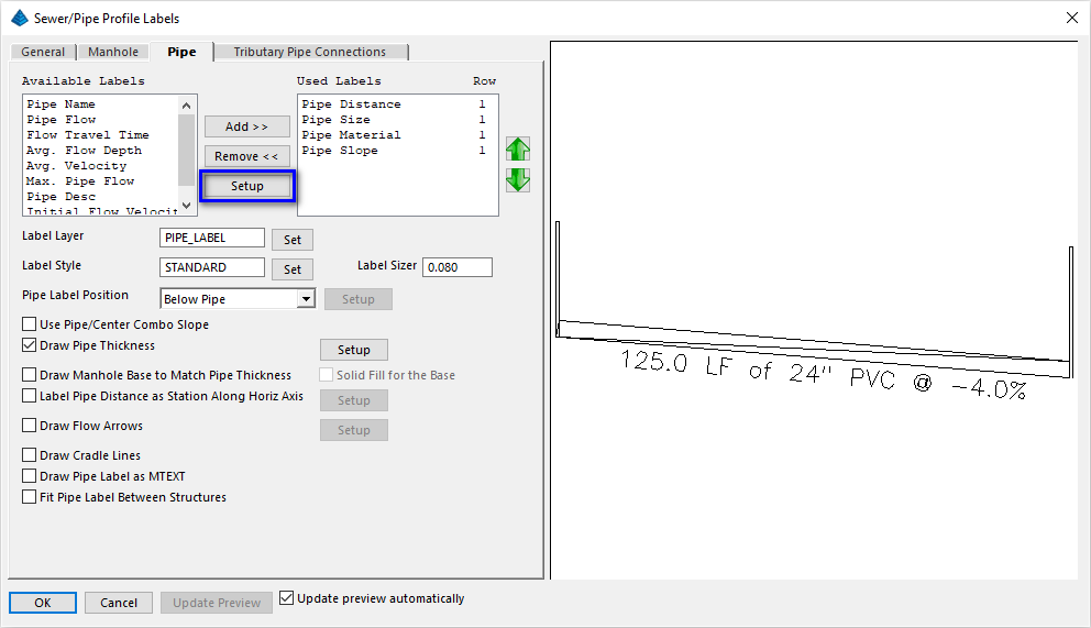
Use the Add >> button to add the following annotation items with the specified settings (use the Setup button to adjust for particular preferences):
| Item | Prefix | Suffix | Other |
|---|---|---|---|
| Pipe Distance | LF | ||
| Pipe Size | of | " | Decimals: 0 |
| Pipe Material | |||
| Pipe Slope | @ | % | Slope Format: % |
Click OK to dismiss the Sewer/Pipe Profile Labels dialog box. Set the Horizontal Scale and Vertical Scale as shown earlier and click OK when ready. When prompted:
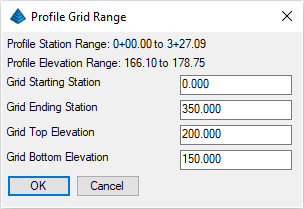
Accept the default values and click OK when ready. When prompted:
Pick Starting Point for Grid <0.00,0.00>: pick a desired location for the profile as illustrated below
NOTE: Some layers frozen for clarity.