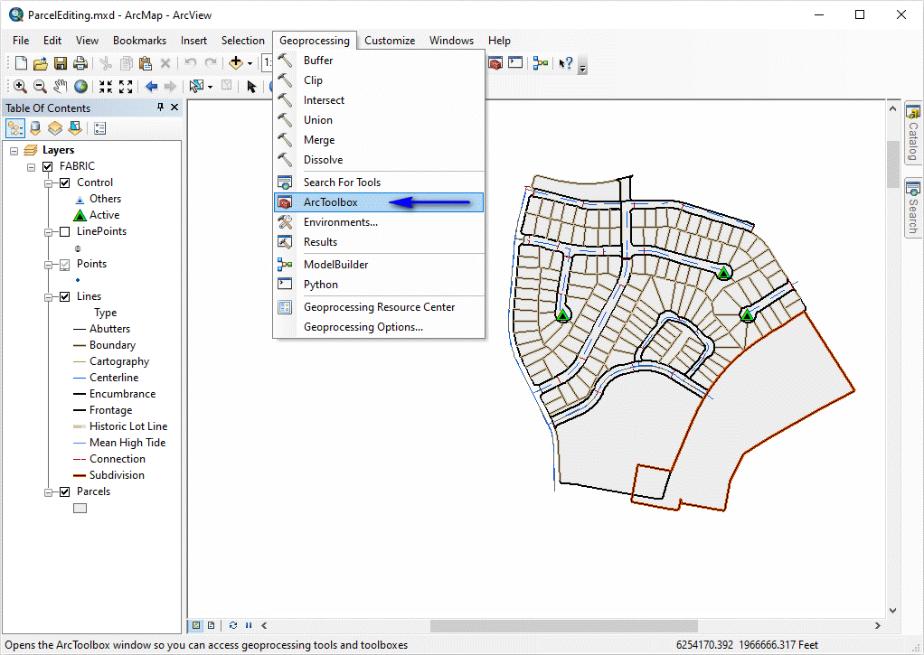
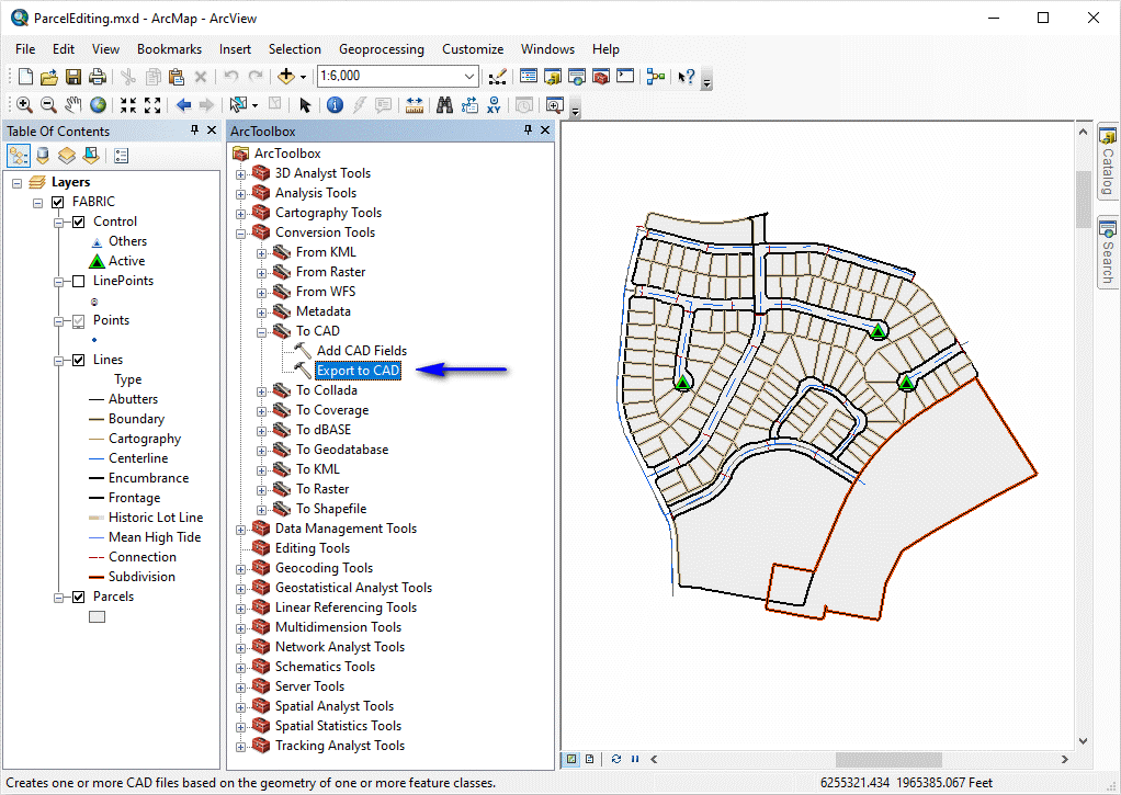
If not already open, launch the ArcToolbox as illustrated above. Issue the ArcToolbox -- Conversion Tools -- To CAD -- Export To CAD as illustrated below:
The next task will be to select the features to export in the Export To CAD dialog box. To select a feature, click the Input Features drop-down list (as illustrated below) and pick a desired feature from the list:
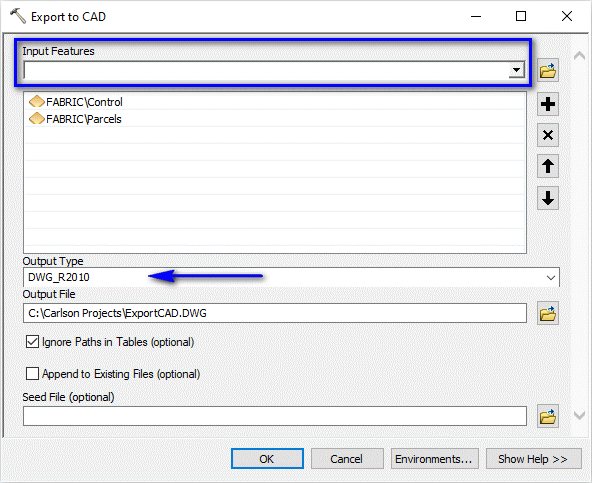
Set the remaining fields as desired including a desired DWG version (Carlson currently suggests the AutoCAD 2010 format for SurvCE users) and a path/filename for the DWG. Click OK when ready.
- If you get the Start Page, pick Open Files.
- If you get the Startup Wizard dialog box, click the Browse button.
- If you are taken directly into CAD, click File -- Open.
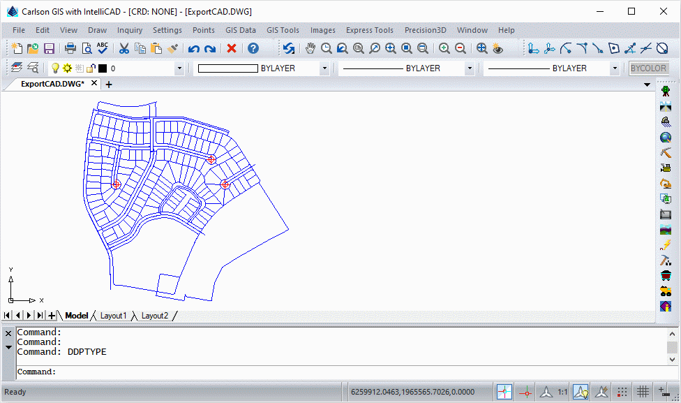
Next, run GIS Data -- GIS Database Settings to display a dialog box similar to that shown below:
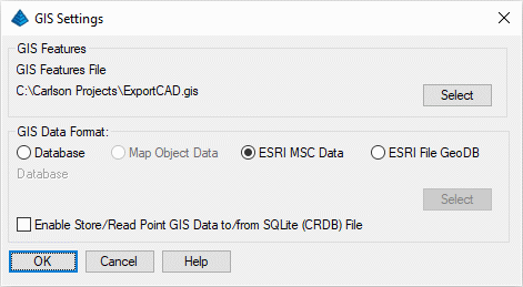
Set the values as shown above and click OK when ready.
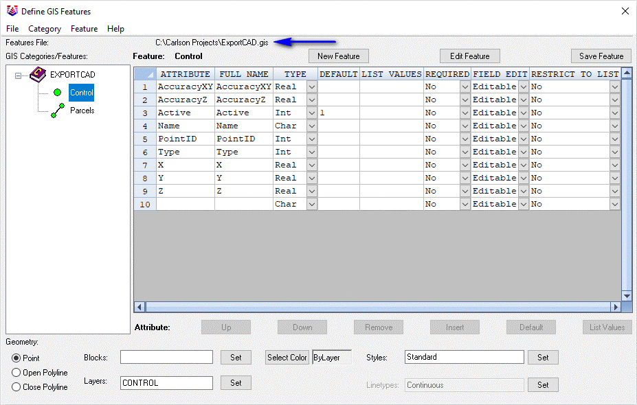
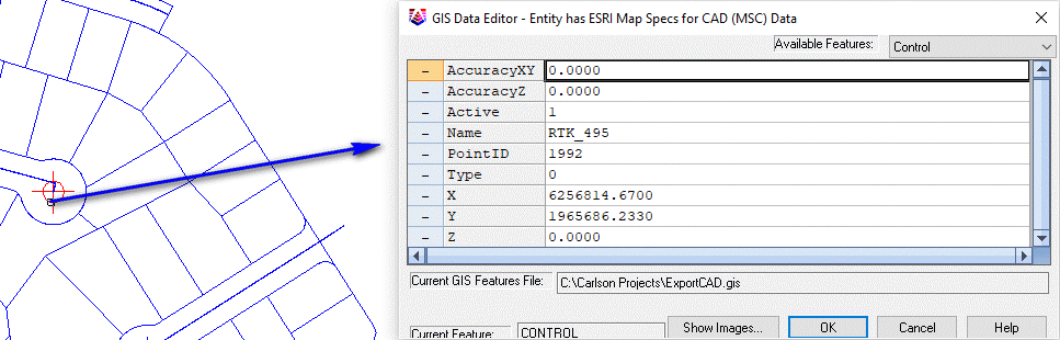
Issue its File -- Import From -- ESRI Map Specs for CAD (MSC) command which should populate the dialog box with the various fields of data as defined by the geodatabase. Dismiss the dialog box via its File -- Save command followed by its File -- Exit command.
NOTE: Some graphical features may not have associated GIS data!
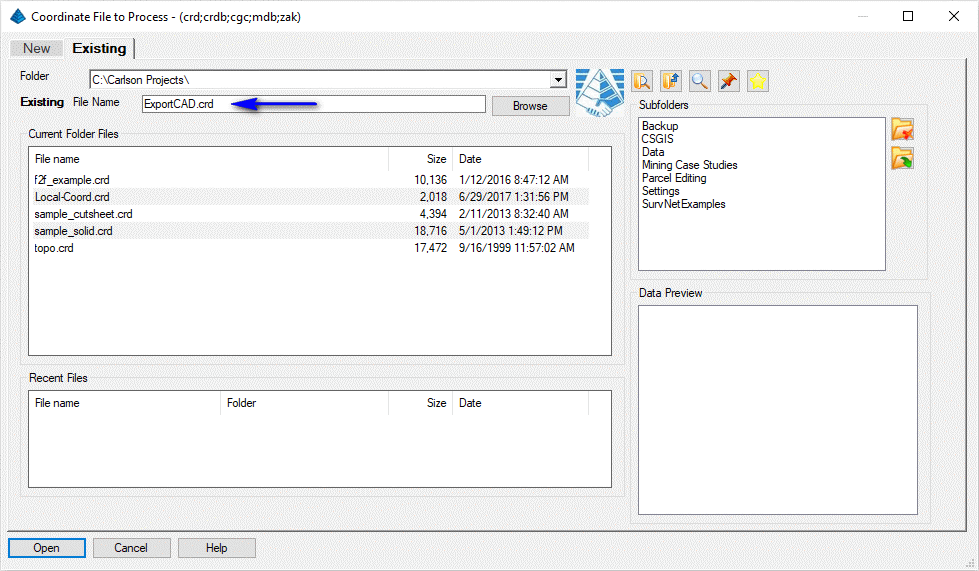
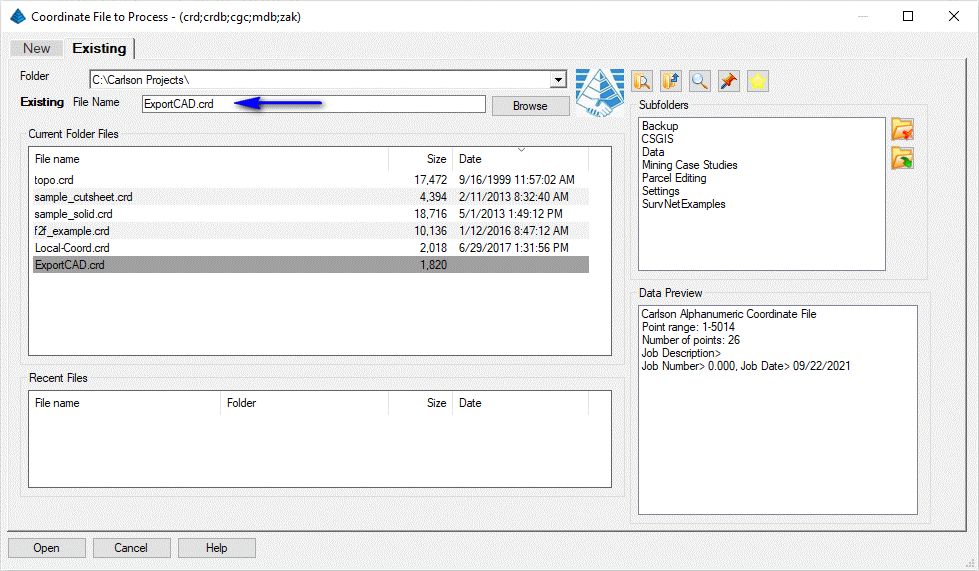
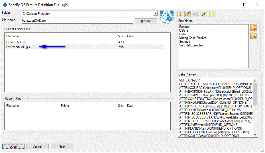
Set the filename as shown above and click Open when ready to display a dialog box similar to that shown below:
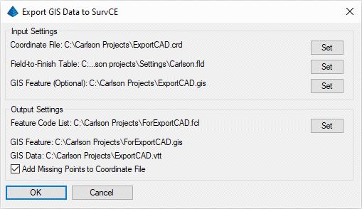
This command takes selected data from the drawing and creates the GIS files that SurvCE uses. Set the values as shown above and click OK when ready. When prompted:
Select entities to export.
[FILter]/<Select entities>: type ALL and press Enter
[FILter]/<Select entities>: press Enter
For a brief summary on the files and content cited above:
For input files:
- Coordinate File: Contains the point database with Point#, Northing, Easting, Elevation and Description.
- Field-to-Finish Table: Defines the coding used by Carlson Survey for the description field that will be converted into a Feature Code List (FCL) for SurvCE.
- GIS Feature: Defines the feature and attribute names. Using this file is optional and applies in case the feature definitions contain more features or attributes than the data entities.
- Feature Code File: This is the SurvCE Feature Code List file for the description field coding definitions.
- GIS Feature: This defines the feature and attribute names. This file is automatically named after the Feature Code File.
- GIS Data: This file contains the attribute data. This file is automatically named after the Coordinate File.
- Add Missing Points to Coordinate File: This option creates points in the Coordinate File for any selected point entities that aren't already in the Coordinate File.
The program will read the GIS data from the selected entities to create the SurvCE GIS data file (.vtt) for SurvCE.
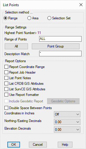
Set the values as shown above and click OK when ready to display the results in the Standard Report Viewer as is illustrated below:
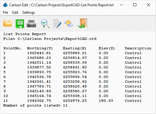
Review the list and click the Exit (Doorway) button to dismiss the report.
- Coordinate File (*.crd) as specified in the Input Files section.
- Feature Code File (*.fcl) as specified in the Output Files section.
- GIS Feature (*.gis) as specified in the Output Files section.
- GIS Data (*.vtt) as specified in the Output Files section.
| Application | Where to Find | Example | |
|---|---|---|---|
| ArcView | View -- Data Frame Properties -- Coordinate System | 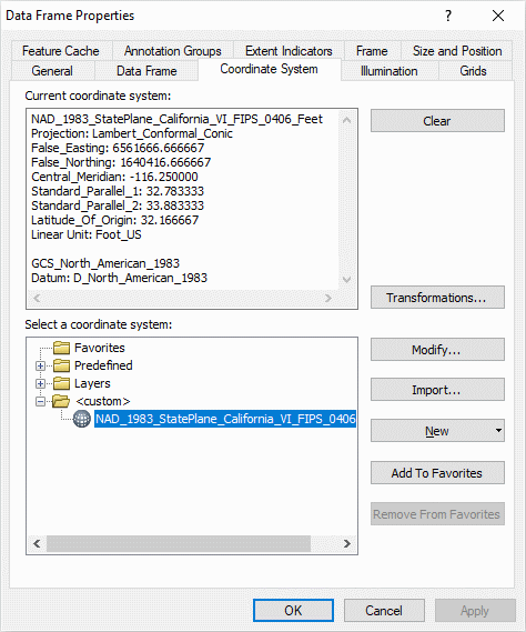
|
|
| Carlson GIS/Survey | Settings -- Drawing Setup | 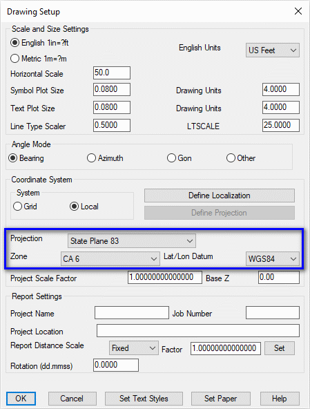
|
|
| Carlson SurvCE/SurvPC | File -- Job Settings -- System tab | 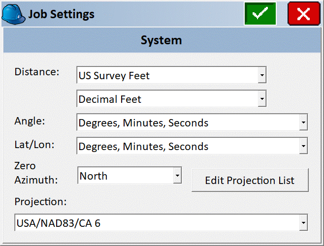
|
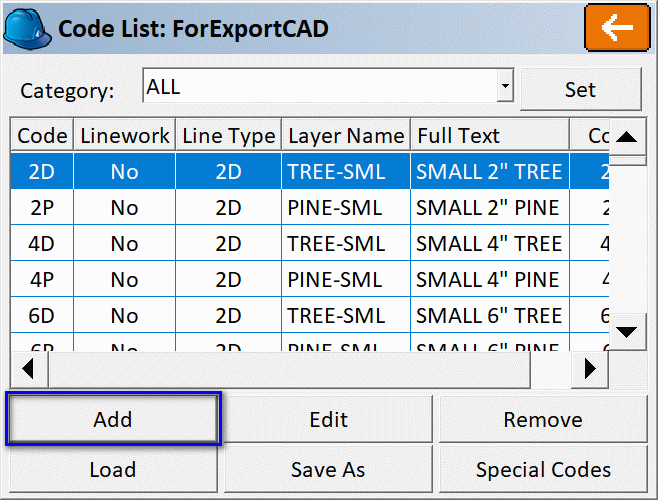
NOTE: If not previously available in the source Field-to-Finish Table (*.FLD) file as specified in the Export GIS Data to SurvCE command above, it would be advisable to Add the code(s) to the SurvCE Feature Code Library as illustrated below:
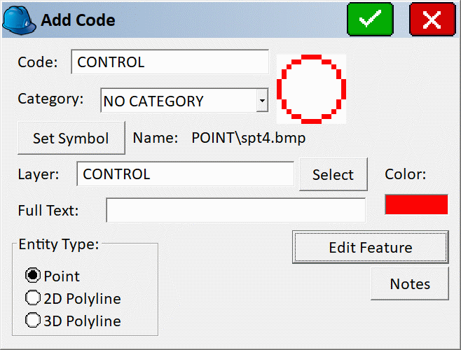
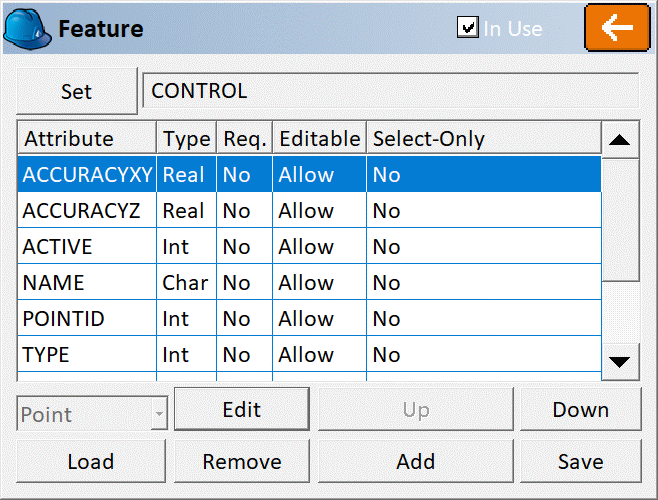
When defined, the associated attributes will be available and presented to the user when the collect a shot using the cited code:
Collect/measure data in the field with SurvCE using conventional data gathering procedures. It is suggested that new features be coded at a point number range in excess of the existing point numbers to prevent confusion.
- Updated Coordinate File (*.crd) as amended by SurvCE.
- GIS Data (*.vtt) as augmented by SurvCE.
- GIS Feature (*.gis) as used in the SurvCE.
- (Optional): DWG/DXF file as produced by SurvCE.
Activate the Survey menu via Settings -- Carlson Menus -- Survey Menu. Issue the Survey -- Draw Field-to-Finish command and make note of the highlighted values illustrated below (as brought over from SurvCE):
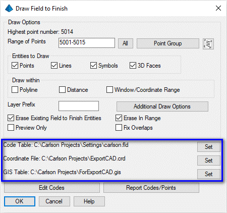
Click OK when ready to place the updated information into the drawing.
Select the *.GIS file that had been placed onto the collector (and possibly modified in the field) and click Open when ready. The DWG entities are packaged into an Esri MSC format. Save and exit from the DWG file.
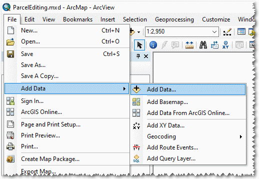
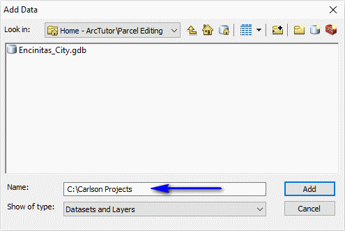
It might be generally easier to indicate the folder path where the DWG file is stored as illustrated below (click Add when ready):
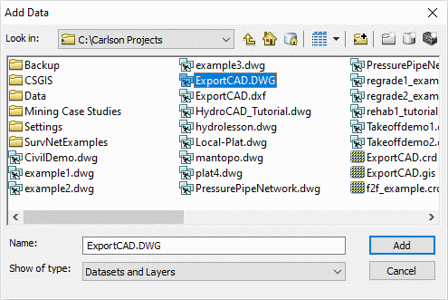
Select the DWG file that was saved earlier and click on the Add button when ready:
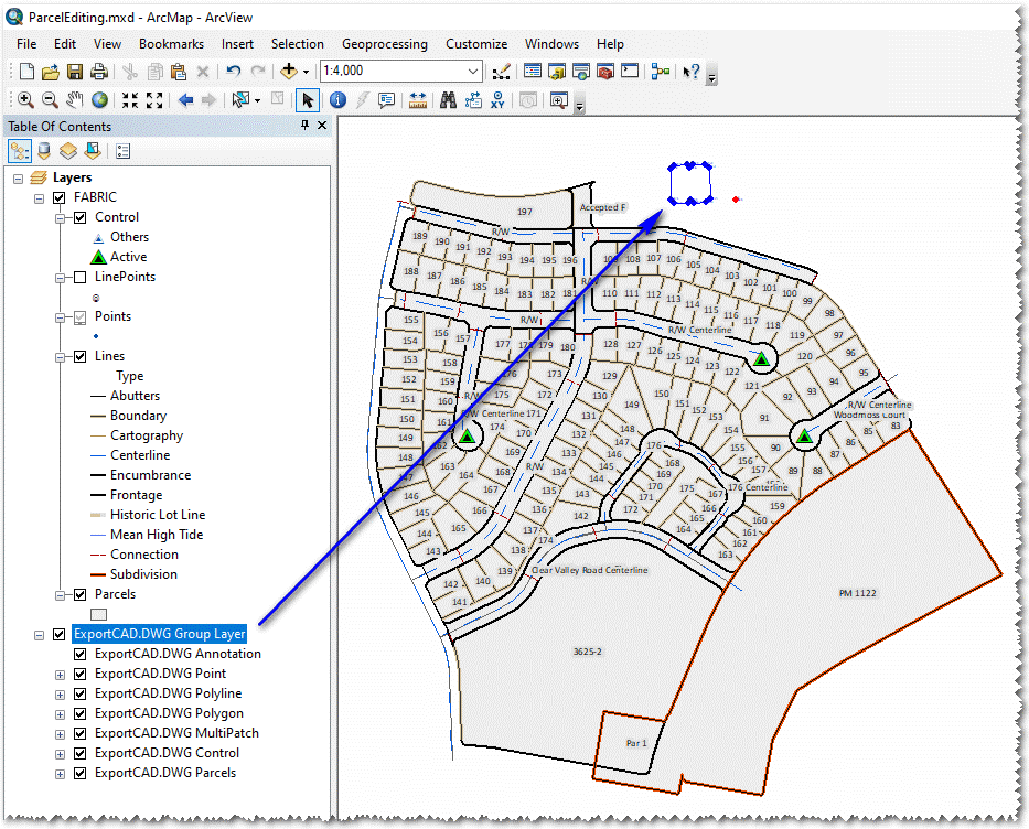
The data is added to the ArcView project as illustrated below: