 View
Control
View
ControlThis command allows you to view a 3D surface in a simulated drive- or fly-over mode. You have the option of following a predefined path such as a road centerline (3D Polyline to follow) or using a user-guided path (free flight). The surface to view can be defined with either screen entities, surface files, or both. The routine offers options for different types of surface shading, direction of travel, viewpoints, vehicles, reference surfaces, light position, color schemes, vertical exaggeration and more.
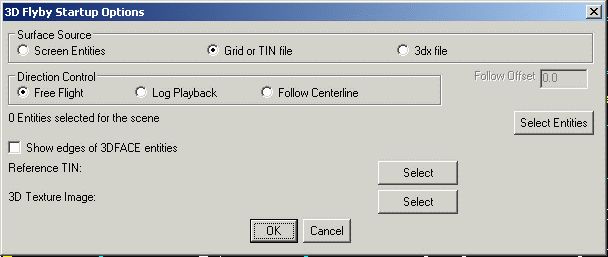 Screen Entities: With this
option enabled, graphically select from the drawing eligible
surface entities including lines, polylines, 3D polylines, 3D
faces, etc. The surface is defined by the selected 3D
Faces. The other entities are just for reference in the 3D
view.
Screen Entities: With this
option enabled, graphically select from the drawing eligible
surface entities including lines, polylines, 3D polylines, 3D
faces, etc. The surface is defined by the selected 3D
Faces. The other entities are just for reference in the 3D
view.
Grid or TIN file: With this option enabled, the surface is defined with either a triangulation file (.FLT or .TIN) or a grid file (.GRD). In addition to the surface file, screen entities may also be selected to be displayed with the surface file. To select the screen entities, press the Select Entities button.
3DX File: This method loads the scene from a 3DX file which can be saved from a previous run of Surface 3D FlyOver. The other 3D viewer commands such as 3D Viewer Window can save the scene to a 3DX file.
Free Flight: This option allows the user to randomly navigate the site, but a starting direction must be defined by picking two points on the screen. Once travel starts, the direction can be controlled with either the right and left arrow icons below the window, or with the arrow keys on the keyboard.
Log Playback: This option uses vehicle log files from Carlson Machine Control to animate the position of vehicles in the scene and show the surface updates.
Follow Centerline: This method prompts for a centerline file (.CL) or alignment polyline to follow. Then the camera view position of the animation is limited to follows this alignment. The Follow Offset allows the view position to be shifted from the alignment which is useful when the alignment is the road centerline and you want to shift the view over to a driving lane.
Select Entities: This must be used for the selection of screen entities when the Surface Source is set to Screen Entities. It can also be used to select additional entities when the surface is defined from a file.Show Edges of 3DFACE entities: For
any selected 3DFACEs, this option will have the viewer show lines
for the edges.
Reference TIN: This loads an optional second surface file (.GRD, .TIN, or .FLT) in the background to report the cut/fill difference between the given surfaces at the current position. This option is only available when the Surface Source is set to Grid or TIN file.
3D Texture Image: This option allows you to drape an aerial image on the surface. This image must be a geo-referenced TIF image that overlaps the area of the surface model. See the Create World File by Image in Drawing for additional information.
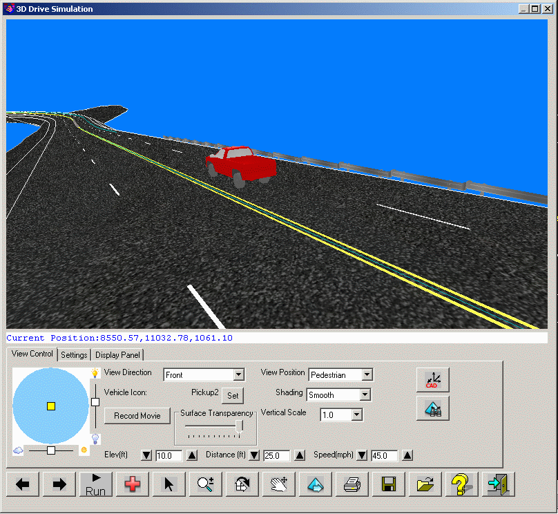
After making the above selections, the 3D graphics window is opened to display the various controls for the drive simulation.
View
ControlView Position: This determines the relative position of the viewpoint in relation to the vehicle. There are three different view positions:
Vehicle Icon: Determines the type of vehicle to be used in the display.
There are many options available, including dozers, sport-utility
vehicles, emergency vehicles and others as setup in the 3D Model
Library command. You also have the option to not display a vehicle
(None).
Record Movie: This function creates
a movie file (.avi) during the animation run. This function prompts
for the .avi file to create and then the video compression method.
The available methods depends on the movie software that is
installed on your computer. Windows has some built-in
methods.
Elevation: This determines the height of the viewer vantage point above the surface. Clicking the up arrow will elevate further from the surface; clicking the down arrow will take you closer to the surface. The Left/Right arrow keys on the keyboard will also control the elevation.
Distance: This determines the horizontal distance from the viewers vantage point (behind) to the actual focal point on the surface. Clicking the Up arrow beside the control will increase the distance from the focal point; clicking the Down arrow will decrease the distance.
Speed: This determines the rate of travel across the surface in miles per hour. Clicking the Up arrow beside the control will increase speed; clicking the Down arrow will decrease speed.
Vertical Scale: This option allows the user to specify a vertical exaggeration factor to aid in viewing flat surfaces with little relief.
Surface Transparency: Use the horizontal slider control to indicate the desired level of opaqueness that should be applied to a surface. A lower opacity results in increased surface transparency and is helpful for viewing sub-surface utilities such as Storm Sewer pipes and manholes.
Shading: Determines the type of shading to be applied to the surface when the surface source is from a file. This option is not active when the surface is defined by screen entities. There are several shading options, including:
 Auto Grading: This option
automatically sets the Grading Tolerance based on the elevation
difference with the reference TIN.
Auto Grading: This option
automatically sets the Grading Tolerance based on the elevation
difference with the reference TIN.
Grading Tolerance: When the cut/fill is less than this
amount, the surface will be colored by the Daylight
Color.
Daylight Color: The surface color for areas with
cut/fill less than the Grading Tolerance.
Reference TIN: When using a Reference TIN from the first
dialog, this option controls the direction of the cut to
fill.
Reference Centerline: When a reference centerline has been selected, the current view position is reported beneath the main viewer window indicating the station/offset relative to the centerline.
Ignore Zero Elevation: Ignores zero elevation entities in the scene.Display Trail: Displays the traveled route on the surface as a line.
Display Cut/Fill: This displays real-time the amount of cut or fill at the
location of the vehicle. This option is only available when a
Reference TIN is used in the first setup
dialog.
Use Software Rendering: This option controls whether to use the computer graphics card for rendering. When the computer has a good graphics card, turning this option off will use the graphics card and result in better performance.
Display Sky: Creates a sky dome of 3D faces around the site that is
colored blue with some clouds. In order to see the sky, your view
point must be below the sky dome. This
feature is only available when the Use Software Rendering is
off.
Display Axis Icon: Shows an x/y/z
axis icon in the scene to help visualize the view
angles.
Display Triangle Edges: Shows lines
along the triangle edges in the scene.
Display Contours: Shows contours for
the surface using the specified Interval.
Dynamic Trace: When enabled, a position marker of the current view point is also displayed in the CAD/DWG window.
Set Colors: This function shows another dialog to set the colors.Surface Color: This setting will determine the color of surface entities when the shading mode is set to either flat or smooth. The color functions are only available when the Surface Source is defined by a File. If the Surface Source is defined by screen entities, color is determined by the properties of the screen entities.
High Color: When using the "Elevation" mode of shading, this sets the color of surface entities that are in the higher elevation ranges of the surface.
Low Color: When using the "Elevation" mode of shading, this sets the color for the surface entities in the lower elevation ranges of the surface.
Model Library: This function manages the collection of 3D models used for the vehicle icons and adding objects to the scene. See the 3D Model Library command for a description of this routine
Set View/Target Points: Provides a dialog box interface that permits the precise location of the viewer vantage point and the precise location of the target view. These coordinate locations are helpful for "view-shed" studies.
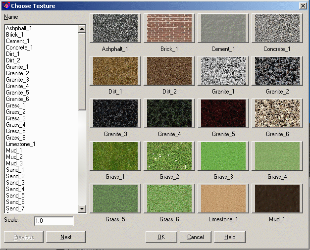
Surface Texture: This function controls the texture for the surface. There
are four Texture Modes.
None: Without a texture, the viewer uses the specified solid
color for the surface.
Single Texture: Sets one texture for the whole
surface.
By Color: Sets a texture for each different color in the
surface. The TIN file can have different colors for different areas
by using the Road Network output TIN options to color by grade or
by using Triangulation File Utilities.
By Color, Single as Default: This is the same as the By
Color option except the Single Texture is used for any TIN colors
not set in the lookup list.

The Edit button uses the Choose Texture dialog to select the
texture. The Scale factor can be used to resize the texture
image.
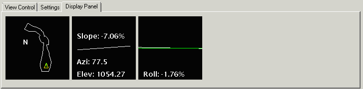
The window on the left shows the overall plan view and the location
of the vehicle of the surface. The middle right displays the
current station (when a polyline is used for direction control),
elevation, slope (in relation to the direction of travel) and
azimuth. The third window on the right indicates amount of roll or
cross slope (in relation to the direction of travel) at your
current position.
| Control | Action |
|---|---|

|
This control represents position of the sun in the sky if looked from above. Therefore, the position of the sun in the center means that the sun is in a zenith, and position near the edge of the circle means that the sun is near the horizon. To move the sun, simply drag it to a new location, or click on the new location. The slide bars on the sides are the intensity and brightness of the display. |

|
When using "Free Flight", this icon turns the direction of travel to the left. |

|
When using "Free Flight", this icon turns the direction of travel to the right. |

|
Starts (or "runs") the animation in the main window. While running, this button becomes the Stop button. |

|
Stops the animation. When stopped, this button becomes the Run button. |

|
When using a 3D polyline for the travel direction, this button returns you back to the original starting position. The simulation must be in the Stopped mode for this to be active. |

|
When using a 3D polyline for the travel direction, this button will reverse the direction of travel at the current position. The simulation must be in the Stopped mode for this to be active. |

|
Converts the left mouse button to a zoom function. |

|
Rotates the main animation window in any X, Y or Z direction by holding down the left mouse button. |

|
Converts the left mouse button to a "pan" function. Holding down the middle mouse button (commonly the scroll wheel button) will also pan. |
| Adds 3D models from the Model Library into the
scene. |
|

|
Switches to "pick" mode so that areas of interest in the view
can be tagged and optionally marked in the CAD/DWG window. As the
pointer is moved, the x, y and z of the current pointer position on
the surface is displayed below the graphics window. Issue a
double-click to tag a desired location and see the Surface Pick Location section below for additional
information. Also, double-click on a 3D model brings up edit
controls to move, rotate or scale the selected 3D model. |

|
"Reloads" the view/scene data and restores the view back to the initial view. |

|
Sets the CAD view direction to be identical to the current view direction. To restore a normal "plan" view orientation in the drawing, from the View menu, click Viewpoint 3D and locate the "plan" or "top" view preset. |

|
Sets the current view identical to that of the CAD view. |

|
Permits the current view to be "printed" to a portable document format (PDF) file for easy distribution to interested parties. |

|
Exits the 3D Surface FlyOver command. |
When a location is "picked" through a double-click, the following dialog box displays with additional controls about how the location should be processed:
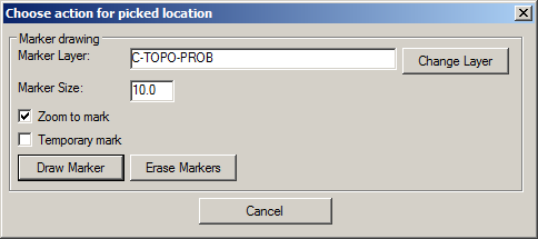
Marker Layer: Indicate a desired layer name or use the Change Layer button to select an existing layer for the position of an eventual marker.
Marker Size: Indicate the desired radius of a circle that will serve as the marker location.
Zoom to Mark: When enabled, the DWG will be zoomed to the location of the marker so it can be quickly found in the drawing.
Temporary Mark: When enabled, the marker will only be displayed in the drawing while the display remains static. As soon as a display update is summoned (via REDRAW, REGEN, ZOOM or PAN), the marker will no longer display on the screen. Disabling this toggle commits a CIRCLE entity into the drawing.
Draw Marker: Draws a marker into the drawing at the coordinates of the picked location and with the display characteristics defined by the Temporary Mark toggle.
Erase Markers: Erases any markers previously placed with the Draw Marker command.
Pulldown Menu Location(s):
Civil → Surface → 3D Views
, Construction → Takeoff
Keyboard Command: flyby , (tk_flyby,
tk_flyby2)
Prerequisite: A Carlson surface model (screen entities or
file) and optionally a 3D polyline.