


This command views in 3D, the selected 3D faces, blocks, polylines, lines and points. This routine uses the OpenGL graphics library for rendering, which gives it superior performance. Some of its features include the ability to zoom in and out, pan, rotate around the X,Y,Z axis and shade in user-positioned lighting. Press the right mouse button and drag to zoom the display.
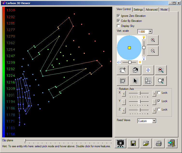
Ignore Zero Elevations: When checked, the 3D viewer ignore entities at zero elevation.
Color By Elevation: This will color the contours or 3D faces by elevation. The elevation scale legend is displayed on the left of the window and can be adjusted via the Color By Elevation Scale controls.
Display Sky: Creates a sky dome of 3D faces around the site that is colored blue with some clouds. In order to see the sky, your view point must be below the sky dome. This feature is only available when the software-only graphics mode is turned off under Carlson Configure → General Settings.
Vert. Scale: Sets the vertical scale factor for the 3D viewer. Relatively flat surfaces can be exaggerated by increasing the vertical scale.
| Control | Action |
|---|---|
|
|
This control represents position of the sun in the sky if looked from above. Therefore, the position of the sun in the center means that the sun is in a zenith, and position near the edge of the circle means that the sun is near the horizon. To move the sun, simply drag it to a new location, or click on the new location. The slide bars on the sides are the intensity and brightness of the display. |
|
|
Zooms In. |
|
|
Zooms Out. |
|
|
Switch to Pan mode. Click and drag to pan. |
|
|
Switch to Rotation mode. When the cursor is placed near the outer edge of the view, a "Z" cursor is presented that permits rotation around the Z-axis. When the cursor is placed further into the interior of the view, an "X,Y" cursor is presented that permits the tilt angle of the view to be adjusted. |
|
|
Switch to initial view. |
|
|
Zoom Previous. |
|
|
Toggles shading on and off for 3DFACE entities selected for the scene. The shading of a 3DFACE is dependent on its "normal" direction and is further controlled by the Shading Mode control. |
|
|
This is an inquire tool. Point the arrow to any entity to display entity data including the layer, type, elevation and length. Double-clicking an entity permits additional actions to be performed on the entity including the ability to change the layer of the entity and/or setting the entity to an elevation of zero (0). |
|
|
Resets the 3D view to plan. |
|
|
Switch to Dynamic Zoom mode. |
Rotation Axis: Permits the use of "slider" controls to orient the view in the X, Y and/or Z axis direction(s).
Fixed Views: Permits the view to be displayed from one of six different directions:
See the Common Controls discussion for additional information.
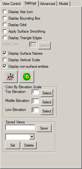
Display Axis Icon: This controls whether to show the X/Y/Z axis icon in the lower left of the graphic window.
Display Bounding Box: This controls whether to display a 3D box around the limits of the data.
Display Orbit: Shows a graphic guide in the viewer for controlling the view angle and position using the mouse movements similar to the AutoCAD Orbit routine.
Apply Surface Smoothing: This option controls the shading of 3D faces either flat by the normals of each 3D faces or smoothed by transitioning with neighboring 3D faces.
Display Triangle Edges: Shows the edge lines for triangles for visualizing the triangles that make up a surface. When active, there is a setting to control the color for these edges.
Display Surface Names: Shows the file names in the viewer for the surfaces currently being viewed.
Display Vertical Scale: This controls whether to display the current vertical scale in the graphic window.
Display Non-Surface Entities: This controls whether to display entities that have been tagged as "non-surface" by the Tag Non-Surface Entities or Points commands.
| Control | Action |
|---|---|

|
Sets the drawing view to match the view shown in the 3D viewer window. |

|
This button sets the view position and target position by coordinates: |

The positions can be entered in the edit boxes or use the respective Pick > button to pick a point in the drawing. The program will pick up the height of the surface for picked points and then the height above the position can be entered. For example to check sight distance, the view position could be a point on a road and height could be the driver eye height and the target position and height could be the object to check.
Color By Elevation Scale: These three colors are used for the Color By Elevation option. The program will interpolate between these colors for the color scale.
Saved Views: This option allows for naming and saving a 3D view for easy recall later. Named views can be selected from the pull-down and the active view can be deleted from the list.
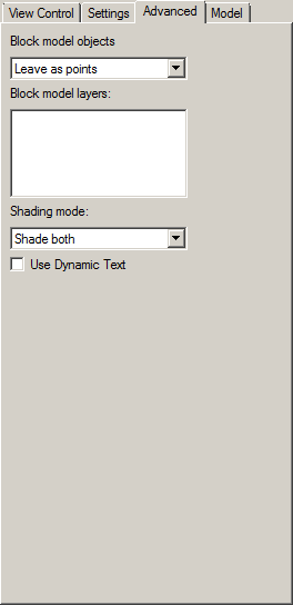
Block Model Objects: This option has three choices when loading block model entities:
Block Model Layers: This will display the block color scheme. Colors of the blocks can be turned on or off to view blocks in the middle.
Shading Mode: When the Shading control is enabled, the rendering of the shaded 3DFACE entities (usually used to represent a surface model) will vary based on:
Use Dynamic Text: This controls whether text objects resize based on the current zoom level or stay the fixed size according to their text size in the drawing.
| Control | Action |
|---|---|

|
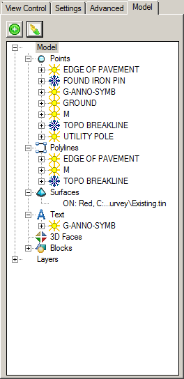
Permits a Carlson Surface Model to be added in to the tree-list (also available as a Surfaces right-click action). |

|
Permits additional visibility and rendering control on the selected item as described below. |
Within the "model" tab is a "tree-view" of the various entities that comprise the view along with the listing of layers upon which the entities are found. Click on the "+" symbol to expand the branches of the tree (or click on the "-" symbol to collapse a branch). Use a Right+Click action on a given item for additional display control:
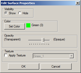
Visibility: Permits the layer or entity to be temporarily hidden from the view.
Color: Permits the color of the layer or entity to be temporarily changed. The Color By Elevation option must be disabled to show the designated color.
Opacity (Surfaces): Use the horizontal slider control to indicate the desired level of opaqueness that should be applied to a surface. A lower opacity results in increased surface transparency and is helpful for viewing sub-surface utilities such as Storm Sewer pipes and manholes.
Texture (Surfaces): When enabled, a material (e.g. grass) can be applied to the view simulation.
| Control | Action |
|---|---|
|
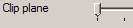
The Clip Plane control permits portions of the view to be hidden from view by adjusting the position of the slider. This is helpful for producing quick "section" views of the data being shown in the view. |

|
This function exports the graphic display to an image file. Several different image file formats are supported including bmp, png, jpg, xpm and gif. There is an Export Image Selections dialog to choose the image resolution and color depth. |

|
Allows the data in the view to be saved to an external 3DX file for subsequent re-use. Use the Saved View option to re-load a desired view. |

|
Allows a previously saved 3DX file to be re-loaded into the current view. |

|
This function outputs the image to a report. For AutoCAD-based configurations, the report format (PDF or DWF) is specified via the Carlson Configure → General Settings. |

|
Exit the 3D viewer window. |
Pulldown Menu Location(s):
View
Keyboard Command: cube
Prerequisite: Entities to display