Input-Edit Centerline File
This command can be used to input a new centerline or edit an
existing centerline (.CL) file. It is a dialog-based alternative to
Design
Centerline and has the advantage of accepting whatever
information you have on your centerlines (coordinates, stationing,
length of tangents and arcs, etc). For creating a new
centerline, it is ideal for entering data straight from highway
design plans. For editing, this command allows you to change any of
the geometric properties of any of the elements of the centerline
(lines, curves, spiral-only and symmetrical spiral-curve-spiral
elements), including the starting coordinates and station.
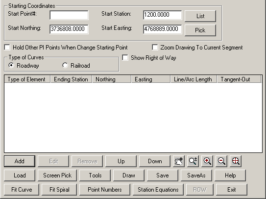
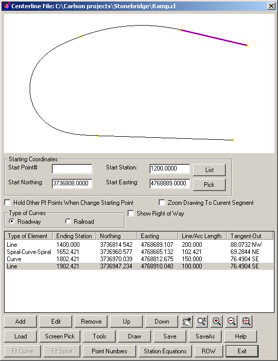
Starting this command launches the Centerline Input-Edit main
dialog box. To edit an existing Centerline, you can either pick the
Load button and pick the .CL file, or pick the Screen Pick button
and pick the polyline in the drawing that represents the
Centerline. The Centerline is then displayed in the graphics window
of the dialog box. The highlighted segment in the text window is
also highlighted in the graphics window.
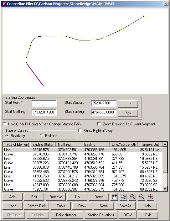
Drag Action (Zoom and Pan):
In the graphics window, hold the left mouse
button down and move mouse to Pan, roll the wheel to
Zoom.
Zoom Drawing To Current Segment:
This option zooms the drawing graphics to
center on the centerline segment currently highlighted in the
dialog.
Hold Other PI Points When Change Starting
Point: With this option active, all the
existing PI's are held when the starting coordinate is moved.
Otherwise, all the PI's are moved by the same amount that the
starting point is moved.
Show Right of Way: This option shows any ROW's defined in the centerline in
the graphic preview window.
Type of Curves: This setting chooses between roadway and railroad
definitions for curve lengths.
Add: Adds a new
element after the highlighted element. Prompts you for the type of
the element to be added, Line, Curve, Spiral-Only or
Spiral-Curve-Spiral.
Edit: Allows
you to edit the highlighted segment.
Remove: Removes
the highlighted element from the centerline.
Up/Down: Moves
elements in the table Up and Down in the list. For example, if this
centerline ended with a tangential line from the last curve, then
was followed by a non-tangential line at 45d NE, moving the last
element up would create a line at 45d after the curve
(non-tangential), and the formerly tangential line will remain
tangential and therefore continue at NE 45d.
Load: Loads an
existing centerline (.CL) file for review or editing. After loading
a centerline, the listbox in the dialog shows a list of all the
elements in the centerline, identifying them as either a line,
curve, spiral only or full spiral-curve-spiral element and
reporting the ending station, northing and easting of the
element.
Screen Pick: Allows user to pick a CL off the screen in the drawing to
load into the editor.
Tools > Reverse: Reverses direction of Centerline.
Tools > Rotate: Rotates the centerline by the specified rotation angle and
around the specified pivot point.
Draw: This
button draws the centerline in the drawing on the specified
layer.
Save: Saves the
currently loaded centerline to a file, or will prompt you for a
name if no name has been set.
SaveAs: Prompts
you for a file name for the saved file.
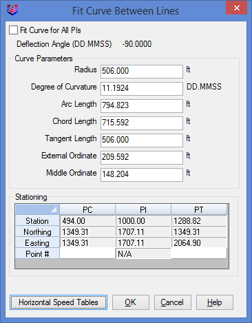
Fit Curve: Fits
a circular curve element into the centerline after the line element
that is currently selected. When all the elements are lines, the
program allows you to fit curve for all PIs. The program checks if
the radius fits all PIs and will prompt the maximum radius that
works for all PIs if the current radius is too big. The Horizontal
Speed Tables allows you to pick a speed and a super elevation rate
to the minimum radius.

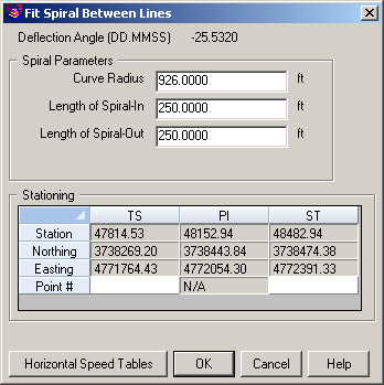
Fit Spiral: Fits a spiral curve element into the centerline after the
line element that is currently selected.
Point Numbers: This will create Carlson points along the elements of the
centerline and store them to the current CRD file. The new points
will be numbered in sequence beginning with the first available
point number in the CRD file.
Station Equations: At any number of locations on a centerline, you can set
the back station and forward station for the re-stationing of the
centerline. The station equation dialog appears below:
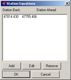
If the Station Back is lower than the Station Ahead, then a
"gap" is inserted in the centerline, where the stations jump
forward. If the Station Ahead is less than the Station Back, then
an overlap occurs, where the common station range is repeated.
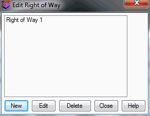
ROW: This function edits the right-of-way
definitions associated with the centerline. There can be multiple
ROW's assigned to the centerline for left and right sides as well
as multiple on the same side. The function first shows a list of
ROW's for the centerline where you can add, edit or delete.
 When you add or edit a ROW, there is
a second dialog for entering the stations and offsets
that define the ROW relative to the centerline. Use negative
offsets for left and positive for right.
When you add or edit a ROW, there is
a second dialog for entering the stations and offsets
that define the ROW relative to the centerline. Use negative
offsets for left and positive for right.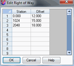 Alternatively, the Enter Right of Way and Polyline to Right of Way commands are
other ways to define the ROW's for a centerline.
Alternatively, the Enter Right of Way and Polyline to Right of Way commands are
other ways to define the ROW's for a centerline.
Exit: Exits
this routine, prompting to save changes if necessary.
The dialog for every type of element shows the point ID, the
northing, easting and station of the start point of the element. It
then allows the user to modify or define the parameters specific to
the type of element. The following are some of the things to
remember about data entry in the centerline editor. These are valid
for lines, curves and spirals.
- Wherever length of the element is to be entered, entering an
expression of the type 123.5 - 93.7 would evaluate the
difference of the values. This is particularly convenient where
only the stations of the start and end points of the element are
known.
- When the station is specified, the program takes the length of
the element as the difference between the station of the start
point of the element and the station specified.
- All bearings should be specified by entering the angle between
0 and 90 degrees (in dd.mmss format) and selecting the
quadrant.
- When entering the delta angle of a curve, only the absolute
value (between 0 and 360 degrees) is to be entered. The direction
of the curve is to be explicitly set as right or left, the default
being left. All angles are entered in (dd.mmss) format.
- Point numbers, when used, access their coordinates in the
current .CRD file. If the point number specified has no coordinates
stored in the coordinate file, the point number is remembered for
that particular location (say the radius point of a curve or the SC
point of a spiral). Then, when the .CL file is saved, the program
creates points for that location and stores them to the .CRD file
with the specified point number.
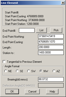
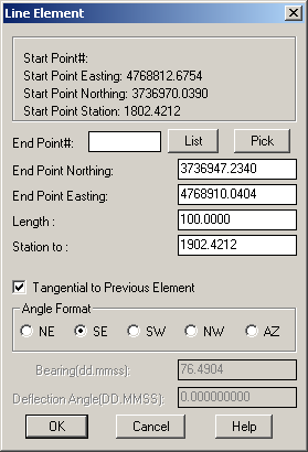
The dialog for a Line allows the user to specify the line
primarily by its length or station and its bearing. The line can
also be defined by its end point number or its coordinates. The
bearing of a line can be changed if the Tangential to the Previous
Element toggle is not checked. By default, any line which follows a
curve element is defaulted to be tangential to it. To use a bearing
different than that of the previous element, uncheck this toggle
and enter the bearing.
The dialog for the Curve allows the user to define the curve
primarily by its radius and delta angle or arc length. The other
parameters of the curve that can be edited are the bearing of
tangent-out and the "Station to", which also defines the arc
length. The curve can also be specified by entering the coordinates
or point numbers of its end point (PT) and the radius point.
Another way to specify the curve would be to enter the chord length
or PT point station and chord bearing. If the central PI point and
a point on the forward tangent are known, then the curve can be
defined by entering both of these points and at least one other
property of the curve (like radius, arc length, delta angle). The
point on the forward tangent can be any point that defines the
tangent out direction including the next PI point. If only the
central PI point is known, then the tangent-out can be entered by
bearing instead of by forward tangent point. Central PI and forward
tangent points are not displayed from the .CL file. They have to be
entered by the user and are valid only for that particular edit
session; that is, they are not remembered the next time the file is
loaded. Curves are assumed to be tangent to the last element unless
the Tangential to the Previous Element checkbox is cleared.
The Curve Edit Mode option defines how the curve is accepted in
the centerline. If the Hold PC point is checked on, the radius is
taken as fixed and the delta angle of the curve is calculated based
on some additional parameter. Hence, the extent of the curve is
unlimited. However, if the Hold PI points option is checked on, the
bearing of tangent-out of the curve is taken as fixed and the
radius is calculated based on some other parameter. In this case,
the curve is completely restricted within the central PI point and
the bearing of tangent out. Hence, when the Hold PI points option
is checked on, the above parameters should also be defined to carry
out the calculations.
The dialog for the Spiral-Curve-Spiral element allows the user
to define the spiral by entering either the various parameters of
the spiral (like the angles and lengths) or the coordinates or
point numbers of its defining points: the TS (Tangent-to-Spiral),
SC (Spiral-to-Curve), Radius point, CS (Curve-to-Spiral), ST
(Spiral-to-Tangent) and end point (optional). While defining the
spiral by its geometric properties, the program will accept the
data even if the information for the simple curve is given with
zero spiral lengths. In this method, however, the central PI point
of the spiral MUST be specified (that is, it is always in Hold PI
Points mode). The tangent out can be defined by entering bearing or
by specifying a point on the forward tangent. This forward tangent
point can be the next PI coordinates. The direction of the
spiral-in and spiral-out elements would be the same as the
direction of the simple curve (left or right). The Spiral
Definition setting chooses between Arc definition for clothoid
spirals and Chord for 10-chord spirals.
The spiral can be defined by several different parameters and
the order that you enter data into the spiral dialog can be
important. There are two main sequences for entering data. The
method to use depends on the spiral data that you have. The first
method is to enter the radius of the simple curve, the spiral in
and out lengths, the tangent bearing out and the PI station. The
second method is to make a Line segment coming up to the TS
(tangent to spiral) point. This Line segment should be added before
creating the Spiral element. Then with the Spiral In point set to
the TS point, enter the radius of the simple curve, the spiral in
and out lengths, the curve direction (left or right) and the arc
length of the simple curve. Then the rest of the spiral points will
be calculated.
The Spiral Only element allows for flexible transitions from
curve to spiral to curve or line to spiral to curve or between any
combination of curve and line elements. The Spiral-Curve-Spiral
element, for example, can be entered as Line, Spiral Only, Curve,
Spiral Only and Line, producing the same results. You can spiral
from tangent to curve, curve to tangent and curve of one radius to
curve of another radius. You can also spiral from one endpoint to
another endpoint. To define the spiral by sweep angle, use the
Delta Angle field. To define the spiral by length, use the Spiral
Length field. To define the spiral by end point, fill in the min
and max radius fields and then enter either the End Point Pnt# or
coordinates and the program will calculate the radius and spiral
length to fit that point.

Once all the elements of the centerline are defined, the file
can be saved and then plotted using the Draw Centerline File
command.
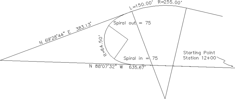
Example
Here is an example of a highway interchange ramp that involves a
starting tangent and a spiral curve that goes abruptly into a
simple curve and then a final tangent. Start by entering a starting
Northing and Easting and starting Station. The Start Point# is
optional. Then the concept is that you click Add to add each
subsequent element (line, curve, spiral-curve-spiral or spiral
only):
Line (Tangent) Segment: We want to enter the tangent segment
length up to the TS (tangent to spiral). Enter in the length
(200.0), bearing (88.0732) and then the bearing quadrant (NW).
Since the next spiral-curve-spiral element can be based on a PI
station, it is not necessary for this line segment to go up to the
TS point. The purpose of this line segment is to establish the
tangent-in direction.
When OK is clicked, the routine will add the Line element as the
first in the list of complete centerline elements. Next up is
Curve-Spiral-Curve. Click Add.

Spiral Segment: Though the dialog is complex (for total flexibility), the
key on a typical symmetrical spiral curve is to enter four things:
(1) the radius of the simple curve, (2) the spiral in and out
lengths, and (3) the tangent-out bearing. Everything else will
calculate when you press Enter for the PI station.
Curve Segment: Add the next element and select curve. The Curve dialog
appears. The key is to enter the Radius Length (255), the Arc
Length (150) and the Curve Direction. Everything else will
calculate.

Final Line Segment: All you need to enter in the final dialog for the line
(tangent) segment is its length. All other items will calculate
when you press Enter.
The completed centerline will appear as shown in the dialog and
each element can be edited. Pick the Save button to store this
centerline data to a .CL file.
Keyboard Command: cledit
Prerequisite: - None -