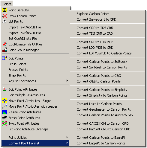
All of the routines in this menu operate on points in a Carlson coordinate (.CRD) file. Coordinate files are binary files that contain point numbers, northings, eastings, elevations and descriptions. The Carlson coordinate database (.CRDB) is based on SQLite and supports point numbers and descriptions up to 255 characters. Alternately, C&G CRD and CGC files, LandDesktop MDB files or Simplicity Systems ZAK files can be used in place of the Carlson CRD file. All routines in this menu will read from, and write to, these types of point data files. At any given time, there can only be one active coordinate file. If a command is initiated that requires a coordinate file while one is not one set, Carlson will prompt for a coordinate file name. From that point on, this is the current coordinate file. Another coordinate file can be used by choosing Set Coordinate File or Open CRD File in Coordinate File Utilities.
Whenever you asked for point numbers, you can enter any combination with commas and dashes or type ALL to use all points. For example 1-3,7,20-23 would act on points 1,2,3,7,20,21,22,23. Coordinate files have either numeric or alphanumeric point numbers. Alphanumeric point numbers consist of nine or less digits and letters (i.e. point# 7A). The type of point number format is set when the coordinate file is created. This setting is found under General Settings in Carlson Configure. This setting only affects new coordinate files.

Each point is drawn by three entities:
The point block is an INSERT entity with PNTNO, PNTELEV and PNTDESC attributes. These attributes represent the point number, elevation and description respectively. The point node is a POINT entity and is used for picking the point with the NODE snap. The point node is also used as the X, Y, Z coordinate in Triangulate & Contour. The symbol can be any symbol defined in the Symbol Library (use SPT0 for no symbol). Since points use Carlson point symbols, the CAD system variables PDMODE and PDSIZE should usually be set to 0.
The points in the drawing can be linked to their coordinates in the coordinate file. The link updates the coordinate file when a point is modified in the drawing. For example, when points are moved with the Rotate Points command, their coordinates will be automatically updated in the coordinate file. To update the coordinate file without this automatic link, you can run the command Update CRD File from Drawing in Coordinate File Utilities. The linking option is called Link Points with Coordinate File (currently only available in AutoCAD) and can be set under General Settings in Carlson Configure. This setting does not affect points currently in your drawing, only points drawn after you change this setting.
Each point in the coordinate file has room for a 32 character description. To have a longer description, an associated point note file can be used. The note file has the same file name as the coordinate file with a .NOT extension and is stored in the same directory as the coordinate file. For example, survey.not would be the note file for survey.crd. The note file is a text file that stores a point number together with the additional notes for the point. There is no limit to the length of the note. Notes can be added to points using the Edit Points command. The List Points command can be used to print out the notes.
For each point, the point attribute block, node, and symbol can be bound together into a "grouped" entity. This means that if you choose to use the Move command (or other CAD tools) the entire collection moves together. This is done using the grouping functionality.
To disable this system altogether, navigate to Carlson Configure > General Settings and turn off the toggle for Group Point Entities. If you need to temporarily disable grouping in a drawing, you can use the AutoCAD toggle for grouping, which is Ctrl-A (holding down the 'Ctrl' key and then pressing the letter 'A' on the keyboard activates this two way toggle and the current status will be echoed to the Command prompt area).
Carlson points include additional information on each element that makes up the point collection (attribute block, node and symbol). This information allows Carlson to know such things as which coordinate (.CRD) the point came from. Commands like Drawing Inspector can then display the point information for the point entities. This also makes it easier for Carlson to identify which drawing objects belong to a point, making commands like Edit Point Attributes a "double-click" pick association instead of a selection set.