Curves Menu
8.02 Inverse Obtuse Curve (OC)
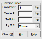
FUNCTION: The Inverse Obtuse Curve routine is used to calculate and report the measurement data along an obtuse circular arc, having a delta angle of greater than 180° (200 grads). This routine calculates the central angle, arc length, chord, chord bearing, tangent and radius of a curve when given the coordinates of the point of curvature (PC), the circle’s center point and the curve’s end point. The routine may also be set to inverse an acute curve or divide an arc into equal segments or intervals.
Activate the Inverse Obtuse Curve routine by picking from the Curves menu; by pressing [Alt][V], [O]; or by typing the two-letter command IC at any data entry prompt.
|
|
TIP: Left-click the [Pts] button to select a point from the Point Manager (see Section 6.09). Right-click the [Pts] button to select a point from the CAD window (see Picking Points in CAD in Section 2.03). |
|
|
TIP: Left-click the [Pts] button to select a point from the Point Manager (see Section 6.09). Right-click the [Pts] button to select a point from the CAD window (see Picking Points in CAD in Section 2.03). |
|
|
TIP: Left-click the [Pts] button to select a point from the Point Manager (see Section 6.09). Right-click the [Pts] button to select a point from the CAD window (see Picking Points in CAD in Section 2.03). |
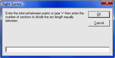
If you choose to enter an interval, you have two choices: You may enter either an arc distance for the intervals, or the number of equal intervals per arc.
To enter an arc length for each interval, simply enter the distance and click [OK] or press [Enter]. To specify the number of intervals per arc, enter an equal sign followed by the number of intervals. For example, and entry of =3 would divide the arc into three intervals
"Sight" Survey will respond to an accepted end point (and interval if so specified) by first checking for a radii match. If the measured difference in radii is greater than 0.01 feet, the message "The radii do not match!" will be displayed.
In a standard Inverse Curve procedure, if the radii match successfully, the program will compute and print into the Text Output window the Central Angle, Radius, Arc Length, Tangent, Chord, and Chord Bearing from the P.C. to the end point. The end point becomes the currently occupied point and the bearing from the end point to the center point becomes the reference bearing for use in the next calculation.
If you have chosen to inverse the curve by interval, the curve will be sub-divided and point numbers will be automatically assigned to the interval points. "Sight" Survey will report the interval points but will not inverse the curve data for each segment.