Points Menu
6.11 Draw All Points (DL)
FUNCTION: The Draw All Points routine is used to quickly draw all of your data points in CAD, or to create point Nodes in AutoCAD or IntelliCAD.
Activate the Draw All Points routine by picking from the Points menu; by pressing [Alt][P], [W] or by typing DL at any data entry prompt.
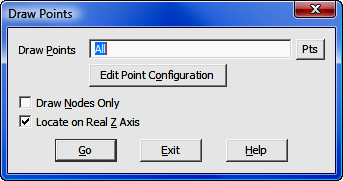
Draw Points: Enter an individual point number, a point string, a point range, of type DF to recall a Defined Figure (see Section 6.20). If any point entered has not yet been assigned coordinates, the program will simply skip that point number.
|
TIP: Left-click the [Pts] button to select a point from the Point Manager (PM - Section 6.09). Right-click the [Pts] button to select a point from the CAD window (see Picking Points in CAD in Section 2.03). Note that is a CAD point has not been assigned you may assign a point number to it at this time. Follow the Enter and Assign procedure (EA - Section 6.01) to assign coordinates and a description to the point. |
[Edit Point Configuration]: Activates the Point Configuration menu (PC - Section 5.08).
Draw Nodes Only: Select this setting to draw only the point entities (nodes) with no annotation. Points can act as nodes to which you can snap objects. You can specify a full three-dimensional location for a point.
Locate on Real Z axis: Select this setting if you want the point entities to be placed into the drawing at the real elevation (z-axis) of the points. If unchecked, the point entities will be drawn at a zero elevation.
AutoCAD/IntelliCAD Options: If you are using AutoCAD or IntelliCAD as your CAD engine, you have additional options available to you in the form of commands entered on the CAD command line. These commands control the appearance of the point nodes. If you are using MicroStation these options are not applicable, since the point node actually consists of a zero-length line and its appearance cannot be altered.
PDMODE: This CAD system variable control the appearance of point objects. PDMODE values 0, 2, 3, and 4 specify a figure to draw through the point. A value of 1 specifies that nothing is displayed. PDMODE values 32-36, 64-65, and 96-100 selects a shape to draw around the point, in addition to the figure drawn through it.
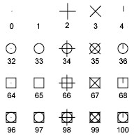
PDSIZE: This CAD system variable controls the size of the point figures, except for PDMODE values 0 and 1. A setting of 0 generates the point at 5 percent of the drawing area height. A positive PDSIZE value specifies an absolute size for the point figures. A negative value is interpreted as a percentage of the viewport size. The size of all points is recalculated when the drawing is regenerated.
You may change PDMODE and PDSIZE settings by entering them on the CAD command line. After you change PDMODE and/or PDSIZE, the appearance of existing points changes the next time the drawing is regenerated (REGEN, or "Sight" Survey command RD).
[Go]: Click this button to draw the specified point(s) in CAD window using the established parameters.
|
NOTES: 1. To draw a particular set of points, you may also use the Plot Points routine. (PP - Section 6.10) 2. To list coordinates in the Text Output window, use the List Coordinates routine. (Section 6.12) 3. To print a coordinate list, select the points in the Point Manager routine (PM – Section 6.09) and click [Print Coordinates]. |