- If you get the Start Page, pick Open Files.
- If you get the Startup Wizard dialog box, click the Browse button.
- If you are taken directly into CAD, click File -- Open.
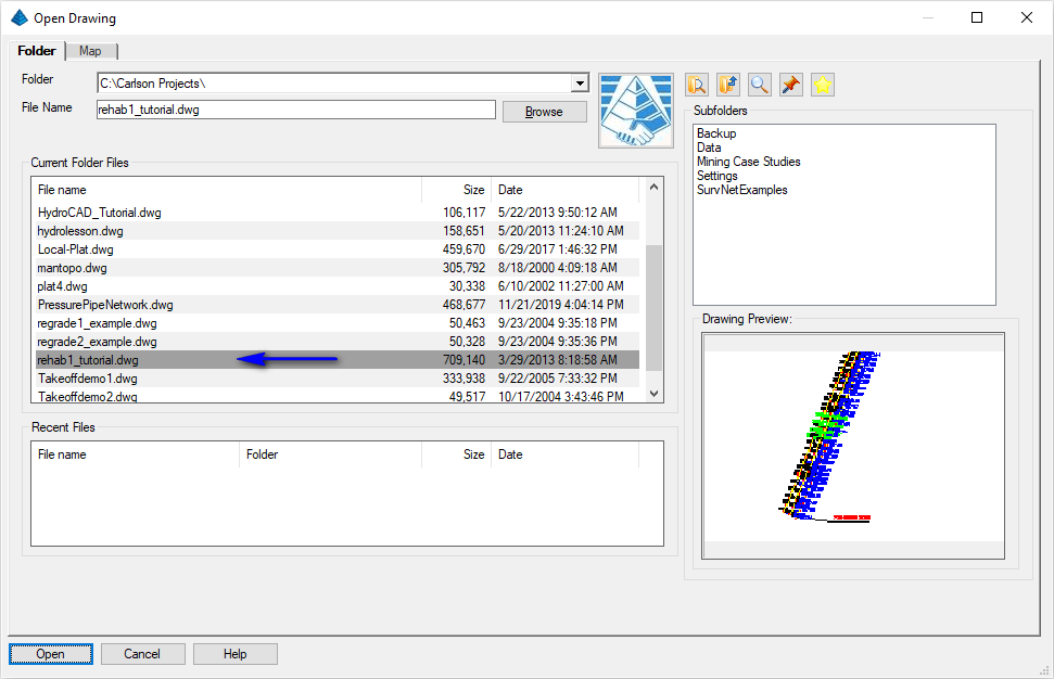
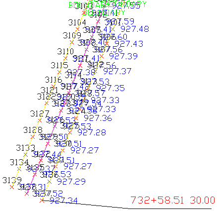
Use the File -- Save As to save a copy named rehab2_tutorial.dwg. Completing this tutorial will alter the drawing file and by renaming the file from the start, you'll keep the original file intact (allowing you to run through the tutorial a second time if desired). This is also a good practice to keep when working on drawings from 3rd parties. The drawing should resemble that shown below:
Ensure you are in the Civil program by issuing the Settings -- Carlson Menus -- Civil Menu command.
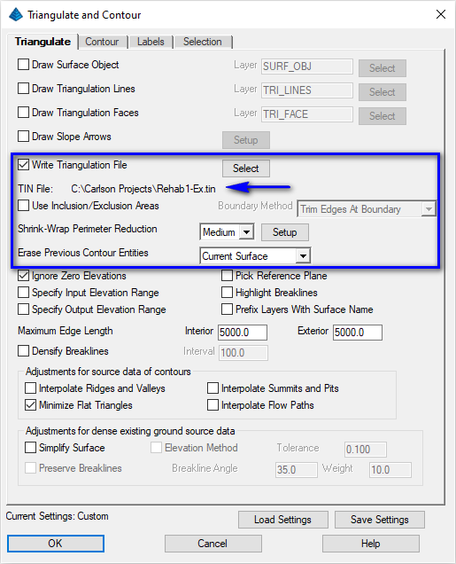
When prompted:
Select the points and breaklines to Triangulate.
[FILter]/<Select entities>: type ALL and press Enter
[FILter]/<Select entities>: press Enter
A surface model (TIN) file representing existing conditions is created.
Pick entities on layers to be frozen: pick one of the pavement edge polylines
Pick entity on layer to be frozen (U-Undo,Enter to end): press Enter
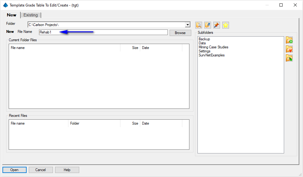
Issue the Centerline -- Polyline To Centerline File to display the dialog box shown below:
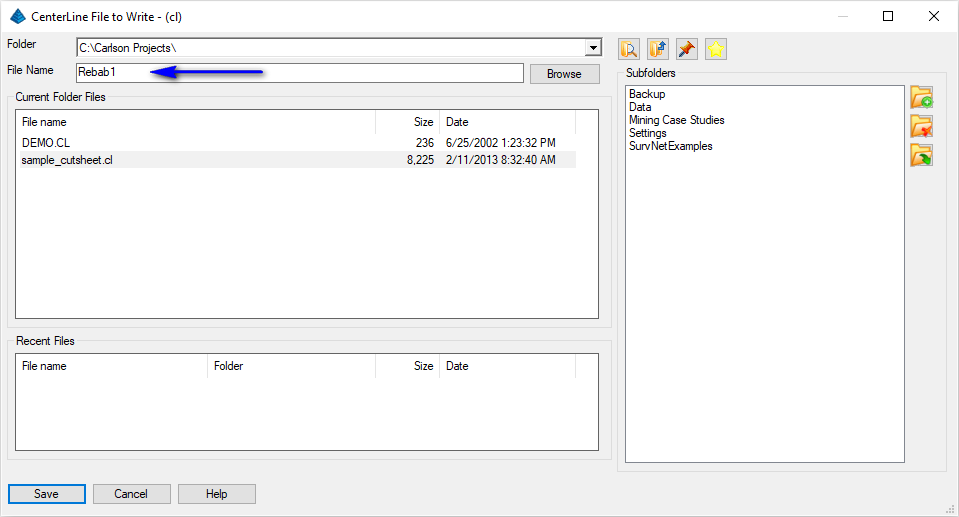 Set the
desired file name as shown above and click Save
when ready. When prompted:
Set the
desired file name as shown above and click Save
when ready. When prompted:Polyline should have been drawn in the direction of increasing stations.
Select polyline that represents centerline: pick the centerline polyline
Centerline station [Reverse/Ending/<Beginning: 0+00>]: type 73258.51 and press Enter
Press ENTER to continue. press Enter
A centerline alignment is created.
NOTE: Double-clicking on the polyline on the screen will open the Centerline Editor command.
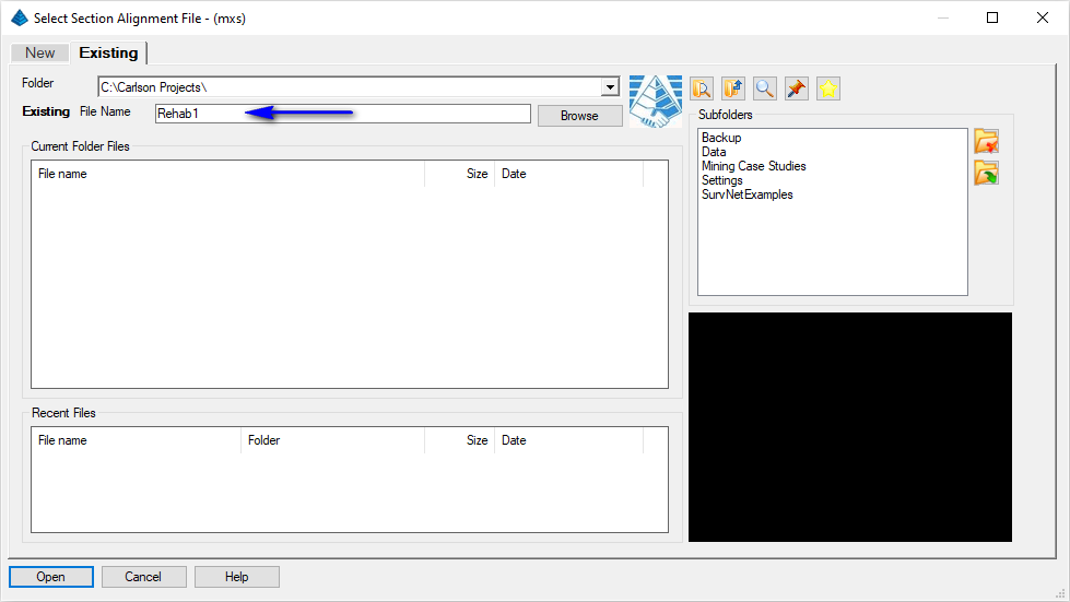
Set the file name as indicated above and click Open when ready. When prompted:
Polyline should have been drawn in the direction of increasing stations.
CL File/<Select polyline that represents centerline>: indicate the Centerline option
Specify a CL File (dialog): selec the Centerline created in the previous step and click Open
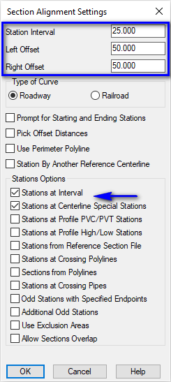
Section Alignment Settings (dialog): set the values as shown below and click OK when ready
The program draws temporary lines in the drawing to show the positions of the sections and displays a summary of the section alignment cross-section stations. Click the Save button followed by the Exit button.
Choose Grid or Triangulation file to Process (dialog): specify the TIN file created earlier and click Open when ready
Section Options (dialog): set the option to Prompt and click OK when ready (with Prompt specified, you'll be prompted if the Section should change if there is an underlying change to the source TIN file)
Section Alignment File to Process (dialog): specify the section alignment (*.MXS) created earlier and click Open when ready
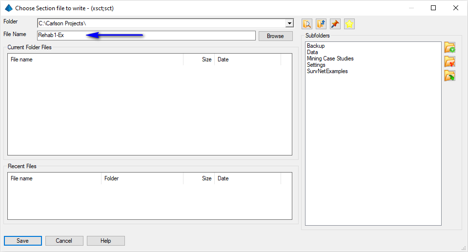
Choose Section File to Write (dialog): specify a file name as illustrated below and click Save when ready
The section file is written.
A large dialog box appears as shown below. In it, you enter segments of the template, which typically work outwards from the middle as you add more lanes, curbs and shoulders. We will enter a symmetrical template, with 12' pavement sections either side of centerline with an 8" subgrade.
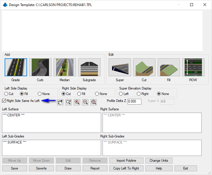
For the lanes, click the Grades icon. This leads to a child dialog as shown next:
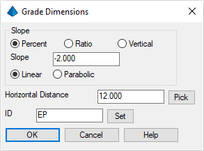
Fill out as shown. It's important to note that a downhill pavement from a crown in the middle is entered as a negative slope. That is, it is -2% heading from centerline outward, regardless of which side of centerline we are speaking of. Slope is independent of the profile grade point. It is also important to enter an ID whenever requested as these can be referenced later for advanced placement control. Click OK and note that the lanes show up in the preview window at the top.
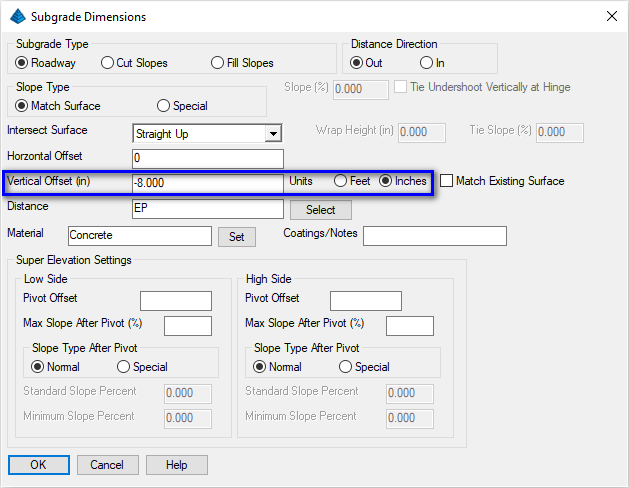
Click the Subgrade button and indicate the following desired values for the subgrade surface:
NOTE:
- Straight Up for the Intersect Surface option instructs the subgrade surface to intersect vertically to the grade surface above.
- 0 for the horizontal offset distance instructs the subgrade surface to start directly under the centerline of the road.
- 8 inches for the Vertical Offset instructs the subgrade to be 8 inches below the grade surface above and will generate the minimum 8" pavement thickness specified earlier in this lesson.
- EP for the Distance instructs the subgrade
width to be the same width as the EP (edge-of-pavement) width
specified in the Grade Dimensions.
NOTE: By using the parametric/variable ID points (e.g. the "EP" code vs the 12' Horizontal Distance, the subgrade width will vary as needed to accommodate the pavement grade width!
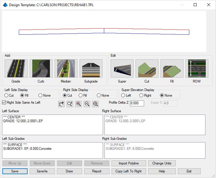
That's all that needs to be defined in the template. Click the Save button and then click Exit.
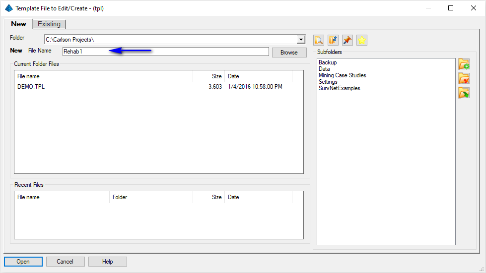
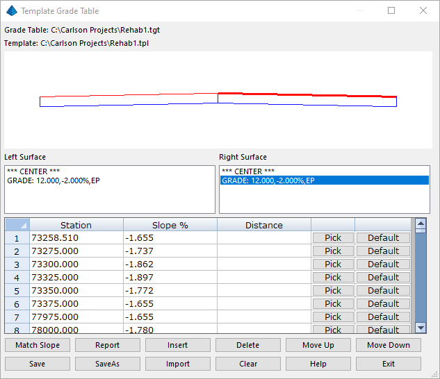
Set the file name as shown above and click when ready. A dialog box similar to that shown below appears:
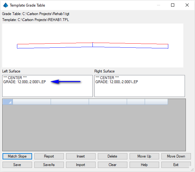
- Highlight the GRADE surface from the Left Surface list, then
- click the Match Slope button, then
- select the section file created earlier as the
Section File to Process and click Open
when ready. A dialog box similar to that shown below appears:
Set the appropriate values for the Left/Right side as shown above and click OK when ready.Match Reference Section Slope Left Side Settings Right Side Settings 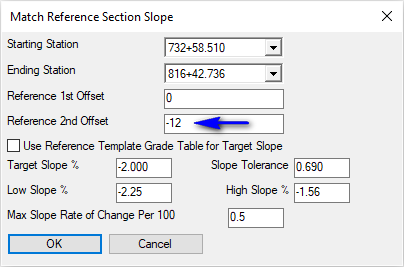
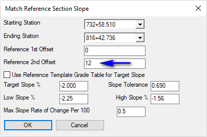
NOTE:- The Reference 1st/2nd Offset values are used to sample the existing sections at the specified offsets to get the existing cross slope.
- The Lowest/Highest Slope % values restrict the design cross-slopes to be within the range specified.
- The Max Slope Rate of Change Per 100 restricts how much the design cross-slope can change between stations. For example, with the maximum set to 0.5 and a cross-slope of -2.0% at station 1+00, the cross-slope at station 2+00 must be between -2.5% and -1.5%.
Set the values as shown above and click OK when ready to display a dialog box similar to that shown below and click OK when ready:
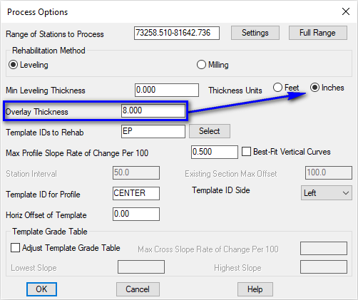
NOTE: The Max Profile Slope Rate of Change Per 100 option is essentially identical to the Max Slope Rate of Change Per 100 value found in Template Grade Table except this one applies to the profile slope instead of the cross-slope.
A profile for the data is generated and any adjustments to the profile can be made through the Profiles -- Design Road Profile -- Road Profile Editor command.
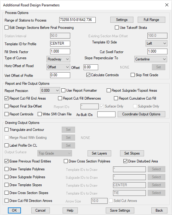
Click OK when ready to continue. On the Additional Road Design Parameters dialog box, accept the default values as illustrated below and click OK to initiate the processing of the design:
The program reports the quantities per station and totals in a report similar to that shown below:
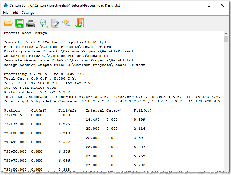
Review the report and click the Exit (Doorway) button when ready.
NOTE: Be aware of the following important values:
- The Total Fill is the amount of extra leveling.
- The Subgrade Volumes are the amount of overlay.
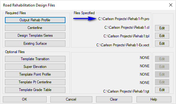
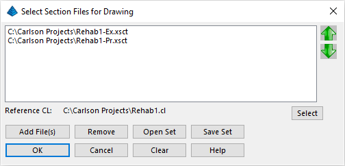 Click the Add File(s) button to add the two
section files we've created earlier and use the Up/Down
arrow buttons to set them in the order shown. Click
OK when ready to display a dialog box similar to
that shown below:
Click the Add File(s) button to add the two
section files we've created earlier and use the Up/Down
arrow buttons to set them in the order shown. Click
OK when ready to display a dialog box similar to
that shown below: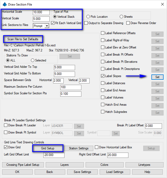
Set the values as shown above paying particular note to:
- Set 10 for the Horizontal Scale value.
- Set 5 for the Vertical Scale value.
- Click the Scan Files to Set Defaults button to "read" the section files specified earlier and retrieve data from them.
- Vertical Stack for the Type of Plot.
- Enable the Label Slopes option and then click
the Set button to ensure:
- Label Section 1 is enabled (use its Set button to enable the Label Below option).
- Label Section 2 is enabled (use its Set button to enable the Label Below option).
Click the OK button and when prompted:
Select Starting Point for Row of Sections <0.00,0.00>: pick a location to the left of the roadway shots
The collection of cross-section stations will be placed into the drawing similar to that shown below:
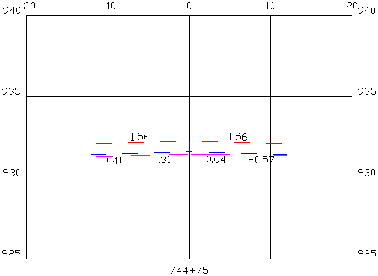
This station shows the existing surface with slopes ranging from 1.41% left to 0.57% right and the design with slopes 1.56% left and right. Since 1.56% was the minimum design cross slope, the design is steeper than existing and there is some leveling needed between the design overlay and the existing.
The profile elevation for this station was set by the right edge since this was the highest point. There is some extra leveling fill needed on the left side. This left side slope can be steeper because our design cross-slope range is 1.56% to 2.25%.
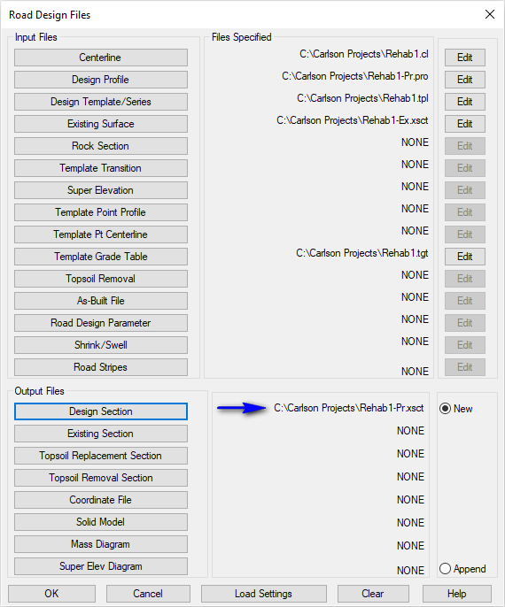
Set the values as shown above and click OK when ready to display a dialog box similar to that shown below. Enable the Adjust Template Grade Table toggle and set the Lowest/Highest Slopes and the Max Cross Slope Rate to the same design parameters used during Template Grade Table as shown below and click OK when ready:
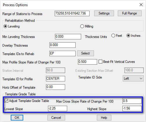
NOTE: The Adjust Template Grade Table option checks the left and right grades while creating the rehabilitation profile and adjusts the slope on the side that is not controlling the profile grade.

Review the report and click the Exit (Doorway) button when ready.
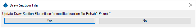
NOTE: Because we had the Link Sections to Files option set to Prompt, let's update the already placed sections! Click Yes on the dialog box shown below:
For this run, the Template Grade Table has been adjusted. In the report, the overlay quantities are the same and the fill quantity for the extra leveling has been reduced as expected. In this case, the Template Grade Adjustment reduced the Total Fill (extra leveling) amount from 463.142 C.Y. to 415.313 C.Y. (about a 10% reduction in needed leveling material) with an updated cross-section representation similar to that shown below:
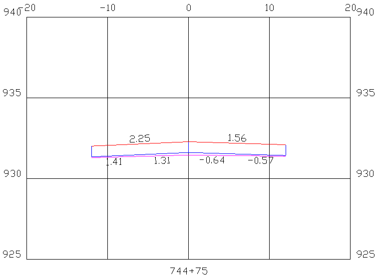
The only difference in the final section is that the left side is steeper to better match the existing surface.