
Draw Menu: Insert
12.07 Title Block (TB)
FUNCTION: The Title Block
routine allows you to insert a pre-defined border and title block centered on the paper.
Activate the Title Block routine by picking from the Draw > Insert menu; by pressing [Alt][D], [I], [B]; or by typing the two-letter command TB at any data entry prompt.
Title Block: Click the button to select the title block from a graphically displayed array.
Scale: Enter the scale factor. This is a relative scale factor and should be left at 1. The title blocks supplied with "Sight" Survey have been created at the actual size indicated in each name. A scale factor of 1 will insert the title block at the correct size for the scale indicated by the CAD Configuration menu (CM - Section 5.03).
Layer: Click [q] to choose the layer upon which to plot the title block, or type in the name of a new layer. The default layer is TITLEBLOCK, which will be created when the title block is inserted into the drawing.
Color: Click [q] to select a color in which the title block will be drawn.
Title Block Text: The title blocks supplied with "Sight" Survey contain attribute fields which will be completed using the text from these text fields. If you do not want any text automatically inserted into the title block, click [Clear Title Block Text]. More information on these attribute fields may be found in the Creating Custom Title Blocks section below.
[Draw Title Block]: Clicking this button transfers control to your CAD application which will prompt you to click the location for insertion of the title block. After placing the title block arrow, focus returns to "Sight" Survey.
Creating Custom Title Blocks
"Sight" Survey includes several title blocks. You can edit any existing title block, or draw your own. Instructions shown below are for IntelliCAD, but AutoCAD instructions are similar.
The title block for this exercise will be designed for an 11 "x 17" sheet. Adjust as needed to make it larger or smaller.
We will start by drawing a rectangle 16" wide x 10” high which will give us a ½” border on all four sides.
|
Command line prompt |
Response |
|
Command: |
rectang [Enter] |
|
Select first corner of rectangle: |
.5, .5 [Enter] |
|
Other corner of rectangle: |
16.5,10.5 [Enter] |
Now we’ll draw the area for tracking revisions in the upper-right corner. Select the line tool or type line at the command line. We will draw the line using X & Y coordinates. Remember that the upper right corner has been established at 16.5 X and 10.5 Y. First we’ll draw the horizontal lines, then the vertical lines, then add text as we reproduce this layout:

|
Command line prompt |
Response |
|
Command: |
line [Enter] |
|
Start of line: |
16.5, 10.25 [Enter] |
|
Angle/Length/End Point: |
11.25, 10.25 [Enter] [Enter] |
|
|
|
|
Command: |
line [Enter] |
|
Start of line: |
16.5, 10 [Enter] |
|
Angle/Length/End Point: |
11.25, 10 [Enter] [Enter] |
|
|
|
|
Command: |
line [Enter] |
|
Start of line: |
11.25, 10.5 [Enter] |
|
Angle/Length/End Point: |
11.25, 9.5 [Enter] [Enter] |
|
|
|
|
Command: |
line [Enter] |
|
Start of line: |
11.75, 10.25 [Enter] |
|
Angle/Length/End Point: |
11.75, 10 [Enter] [Enter] |
|
|
|
|
Command: |
line [Enter] |
|
Start of line: |
14.5, 10.25 [Enter] |
|
Angle/Length/End Point: |
14.5, 10 [Enter] [Enter] |
|
|
|
|
Command: |
line [Enter] |
|
Start of line: |
15.5, 10.25 [Enter] |
|
Angle/Length/End Point: |
15.5, 10 [Enter] [Enter] |
This completes the lines for the revision tracking area. Now we’ll draw the bottom section of the title block.
|
Command line prompt |
Response |
|
Command: |
line [Enter] |
|
Start of line: |
16.5, 2.25 [Enter] |
|
Angle/Length/End Point: |
10.25, 2.25 [Enter] |
|
Angle/Length/End Point: |
10.25, .5 [Enter] [Enter] |
|
|
|
|
Command: |
line [Enter] |
|
Start of line: |
12.25, 2.25 [Enter] |
|
Angle/Length/End Point: |
12.25, .5 [Enter] [Enter] |
|
|
|
|
Command: |
line [Enter] |
|
Start of line: |
12.25, 1.75 [Enter] |
|
Angle/Length/End Point: |
16.5, 1.75 [Enter] [Enter] |
|
|
|
|
Command: |
line [Enter] |
|
Start of line: |
10.25, 1.14 [Enter] |
|
Angle/Length/End Point: |
12.25, 1.14 [Enter] |
|
Angle/Length/End Point: |
16.5, 1.14 [Enter] [Enter] |
|
|
|
|
Command: |
line [Enter] |
|
Start of line: |
10.25, .82 [Enter] |
|
Angle/Length/End Point: |
12.25, .82 [Enter] |
|
Angle/Length/End Point: |
16.5, .82 [Enter] [Enter] |
|
|
|
|
Command: |
line [Enter] |
|
Start of line: |
16, 1.14 [Enter] |
|
Angle/Length/End Point: |
16, .82 [Enter] [Enter] |
|
|
|
|
Command: |
line [Enter] |
|
Start of line: |
13.5, .82 [Enter] |
|
Angle/Length/End Point: |
13.5, .5 [Enter] [Enter] |
|
|
|
|
Command: |
line [Enter] |
|
Start of line: |
15, .82 [Enter] |
|
Angle/Length/End Point: |
15, .5 [Enter] [Enter] |
This completes the lines for the lower title block. At this point let’s set our border lines to a bolder stroke. Select Edit > Select All or simply press [Ctrl][A] to select everything in the drawing. Now double-click your mouse on one of the selected lines, or type entprop [Enter] on the command line (AutoCAD users type properties [Enter]). When the Properties dialog appears, set your Line Thickness to 2 and click [OK]. Now we’ll add the actual corners of the paper which will prove to be useful when plotting your drawing. Using these corners, you will be able to plot the contents bounded by a window which is selectable by clicking on the opposite corners of the paper corner indicators. We will use two - 1” line segments at each corner.
|
Command line prompt |
Response |
|
Command: |
line [Enter] |
|
Start of line: |
0, 1 [Enter] |
|
Angle/Length/End Point: |
0, 0 [Enter] |
|
Angle/Length/End Point: |
1, 0 [Enter] [Enter] |
|
|
|
|
Command: |
line [Enter] |
|
Start of line: |
0, 10 [Enter] |
|
Angle/Length/End Point: |
0, 11 [Enter] |
|
Angle/Length/End Point: |
1, 11 [Enter] [Enter] |
|
|
|
|
Command: |
line [Enter] |
|
Start of line: |
16, 11 [Enter] |
|
Angle/Length/End Point: |
17, 11 [Enter] |
|
Angle/Length/End Point: |
17, 10 [Enter] [Enter] |
|
|
|
|
Command: |
line [Enter] |
|
Start of line: |
16, 0 [Enter] |
|
Angle/Length/End Point: |
17, 0 [Enter] |
|
Angle/Length/End Point: |
17, 1 [Enter] [Enter] |
Before we start adding text, let’s set our text font and size. At the command line, type style [Enter]. In the Text Style dialog, select the desired Text Font. We’ll select Arial for this example. Click [OK]. Now we’ll place some text headings in the lower title block. For these heading we will just select our text entry points by entering coordinates that are just a few hundredths inside and below the border lines of the cells we are labeling. We could also just “eyeball” in the location by clicking on the drawing, then move the text around later to fine-tune our spacing.
|
Command line prompt |
Response |
|
Command: |
dtext [Enter] |
|
Start point: |
12.3, 1.03 [Enter] |
|
Height of text <0.2000>: |
0.06 [Enter] |
|
Rotation angle of text <0> |
[Enter] |
|
Text: |
DRAWING FILE [Enter] [Enter] |
|
|
|
|
Command: |
dtext [Enter] |
|
Start point: |
16.06, 1.03 [Enter] |
|
Height of text <0.0600>: |
[Enter] |
|
Rotation angle of text <0> |
[Enter] |
|
Text: |
REV [Enter] [Enter] |
|
|
|
|
Command: |
dtext [Enter] |
|
Start point: |
12.3, .70 [Enter] |
|
Height of text <0.0600>: |
[Enter] |
|
Rotation angle of text <0> |
[Enter] |
|
Text: |
SCALE [Enter] [Enter] |
|
|
|
|
Command: |
dtext [Enter] |
|
Start point: |
13.55, .70 [Enter] |
|
Height of text <0.0600>: |
[Enter] |
|
Rotation angle of text <0> |
[Enter] |
|
Text: |
DRAWN BY [Enter] [Enter] |
|
|
|
|
Command: |
dtext [Enter] |
|
Start point: |
15.05, .70 [Enter] |
|
Height of text <0.0600>: |
[Enter] |
|
Rotation angle of text <0> |
[Enter] |
|
Text: |
SHEET [Enter] [Enter] |
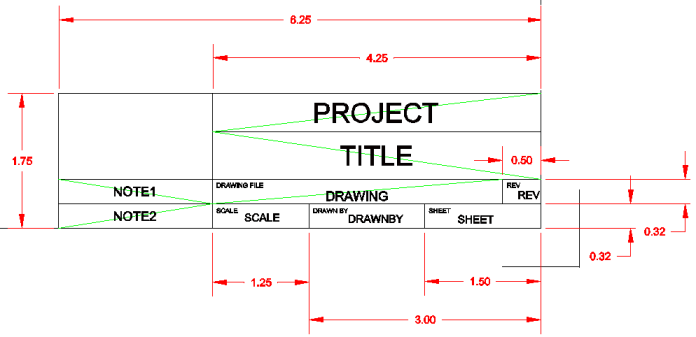
Now continue with text in the top title block. We will locate these headings, as well as the rest of our text, directly in the middle of each respective cell. To help us locate the middle, we will begin by drawing some lines diagonally across each cell. To locate the text, we will snap to the mid-point of the polyline segment. We will remove the polylines after we insert text. For illustration, the polylines are shown in green, although setting a different color for the temporary polylines is not necessary. Start by typing osnap [Enter] at the command line, then type end [Enter]. This will allow us to snap to the exact corners of each cell.
|
Command line prompt |
Response |
|
Command: |
Polyline [Enter] |
|
Start of polyline |
Click at the top left corner of the top cell in the top title block |
|
<Next point>: |
Click at the lower right corner of the top cell in the top title block |
|
<Next point>: |
In a similar manner, click at diagonal corners in the remainder of the cells. When you have clicked on the last point, press [Esc]. |
|
|
|
|
In the same manner, draw diagonals in the lower title block as shown by the green polylines in the example drawing. |
|
Now we will place text in the upper title block. The text will be inserted at the mid point of each segment of the polyline as it crosses the cell. This will insure us of perfectly centered text. We will set up our snaps to pick the mid-point of the line. At the command line type: osnap [Enter] mid [Enter].
|
Command line prompt |
Response |
|
Command: |
dtext [Enter] |
|
Start point: |
M [Enter] (to middle-justify text) |
|
Center point of text: |
Click near the midpoint of the diagonal in the top cell. You will automatically snap to the mid-point of the line. |
|
Height of text <0.0600>: |
.1 [Enter] |
|
Rotation angle of text <0> |
[Enter] |
|
Text: |
REVISIONS [Enter] [Enter] |
|
|
|
|
In a similar manner, enter the rest of the text for the second line. |
|
“Sight” Survey allows for the use of attributes when placing text. This means that as the title block is place, certain attributes (or information) may be automatically placed into the title block. The Title Block Text portion of the Title Block dialog (as shown below) contains several fields into which you can place information about your project. This information is used to populate attribute fields in the title block. You may also use these fields to place information into your custom title blocks as long as you insert the properly named attribute fields. The titles (or tags) for each field indicate the attribute name recognized by “Sight” Survey for that piece of information.
The table below shows the attribute name (tag), the default value, the font, size, and justification. The font and size may be adjusted as desired.
|
TAG |
DEFAULT VALUE |
FONT |
HEIGHT |
JUSTIFICATION |
|
Project |
Your Job Name |
Arial |
0.25 |
Center-Middle |
|
Title |
Your Job Name |
Arial |
0.25 |
Center-Middle |
|
Drawing |
Your Drawing Name |
Arial |
0.12 |
Center-Top |
|
Rev |
|
Arial |
0.12 |
Left-Middle* |
|
Scale |
As set on Config>CAD |
Arial |
0.12 |
Left-Middle* |
|
Drawn By |
|
Arial |
0.12 |
Left-Middle* |
|
Sheet |
|
Arial |
0.12 |
Left-Middle* |
|
Note1 |
|
Arial |
0.18 |
Center-Middle |
|
Note2 |
|
Arial |
0.18 |
Center-Middle |
*No polyline was drawn to snap to this location. Simply click your mouse at the desired text location. After placing the tag text you may use your mouse to adjust the positioning. Since you will not be using snaps to locate this text, draw this text last and turn off osnaps prior to selecting these insertion points. At the command line type: osnap [Enter] off [Enter].
Defining the Attributes: Select Tools > Define Attributes, or type DDATTDEF [Enter] on the command line.

Name: Enter the attribute TAG name here.
Prompt: Enter a prompt that will appear on the command line if you manually insert the title block into your drawing (not using “Sight” Survey’s Title Block routine).
Default Text: Enter the attribute TAG name here. This is the text that will appear on the drawing prior to the insertion of the attribute text.
Insert Coordinates: Click [Select] to set the insertion point. With osnaps set to MID, click on the middle of the polyline that crosses the cell. With osnaps set to OFF, simply click on an insertion location.
Text Style: Select a text style or leave it set to Standard.
Justification: Click [q] to select the justification.
Text Height: Click [q] to select the text height.
Rotation: Click [q] to select the rotation angle.
[Define]: Click [Define] to insert the attribute into the drawing, then continue with additional attributes. When you are finished, click [Define and Exit].
Use these basic instructions and the data in the attribute table above to define all your title block attributes.
All that remains is to clean up and save the drawing. To delete the polylines that were used to center the text, simply click on each polyline and press [Delete].
If we set the color attribute to BY BLOCK, “Sight” Survey will insert the title block using the color selected on the Title Block dialog box. Select Edit > Select All or simply press [Ctrl][A] to select everything in the drawing. Type entprop [Enter] on the command line (AutoCAD users type properties [Enter]). When the Properties dialog appears, click [Select Color] to launch the Color dialog. Set the color to BY BLOCK and click [OK]. Click [OK] on the Properties dialog to close it.
Finally, we need to save our title block. Click File > Save and save your work as an AutoCAD drawing (*.dwg). There are two requirements you must follow or you will not be able to access your title block from within “Sight” Survey:
You must start your file name with TBLK followed by a space, such as TBLK 17 x 22.dwg. The “TBLK” indicates to “Sight” Survey that this file should appear on the title block list.
You must save your file in “Sight” Survey’s Symbols file folder. This location is: C:\Program Files\Simplicity Sight Survey 2009\Symbols