The Scene Tab allows customization of the currently
active scene's drawing options. The Scene Tab will be blank
until you open a scene from the Project Tab using the
View command.
It is important to note that the controls in the Scene Tab will
vary depending on several variables such as the view mode and which
entities are displayed or selected in that scene.
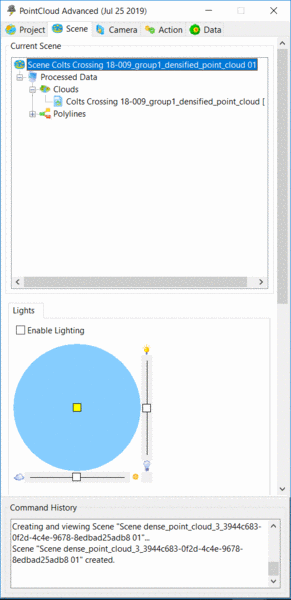
The two sliding scales control the Light Intensity (vertical control) and the Ambient Intensity (horizontal control).
The Light Intensity controls the intensity of the directional
light, which is a light, positioned to simulate the effect of a
distant light source like the sun.
The Ambient Intensity controls the intensity of the ambient
lighting, which is the base light level that affects everything
regardless of the surface normal.
The Center Light control can be moved freely to change the position of the light source.
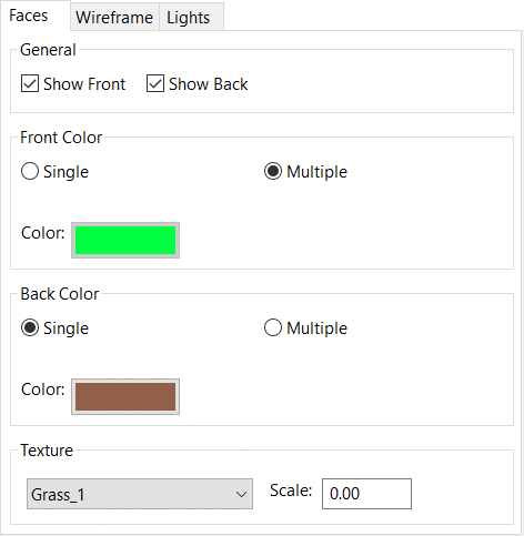
When viewing a TIN, controls for Faces will become active.
Show Front - toggles the display of the front TIN faces in
the current view
Show Back - toggles the back (or underneath) faces of the
TIN in the current view
Front and Back Colors can be set separately
Texture can be set for the overall TIN appearance
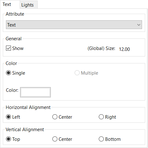
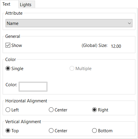
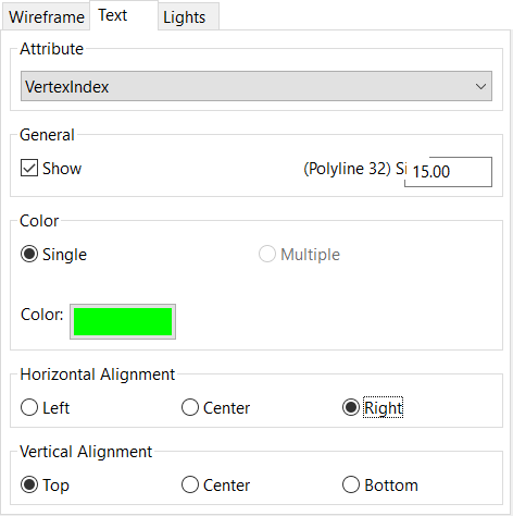
The Text properties page controls how the viewer will draw an
object's text elements. It contains controls to Show the text,
color and options that pertain specifically to the text's
alignment. Changing the alignment will not change the origin of the
text, merely how the text is displayed in relation to that origin.
Additionally, some objects can have several text elements, so you
will have to specify which text attribute you want to modify in the
Attribute drop down box.
Point Size will change the visible size of the points in
the active data in the Viewer. This does not alter the data itself,
just the view.
Maximum Cloud Points Per Scene - controls the maximum points
that can be displayed for each scene. This allows users to control
the graphic display for their computer.
Maximum Display Density -
controls the density of the points in
view prior to limiting the overall scene. If the density is lower,
the cloud may appear thinner but display faster. If the
density is increased, the display may
show more points in the denser areas but reach the Maximum Cloud
Points Per Scene quicker.
Regions if classified, can be controlled and selected based on
those classifications. By toggling the radio buttons next to each
classification, the user can isolate and/or select different
portions of the cloud.
New Region From Selection can be created by first making a
selection from one or more existing regions, or by selecting a
portion of the cloud from the Action tab and then creating a
region from that selection.
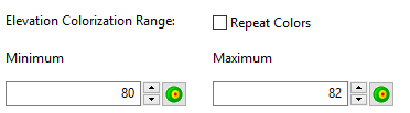
When viewing a cloud in Position/Elevation mode, different
controls will be displayed in the Scene dialog box.