The Action Tab is the fourth tab in the Point Cloud Manager. All data extraction, as well as virtual surveying, is done here in Carlson Point Cloud. A Scene with 3D data must be currently opened for the controls in the Action tab to be enabled; otherwise they will be greyed out.
The Action functions that can be used with a Scene are broken up into five different Panels: Selection Set, Edit, Transform, Create, and Extract.
The four radio buttons at the top of the Selection Set panel operate as two sets and determine the behavior of the selection methods (Individual, Window, Perimeter and Polyline).
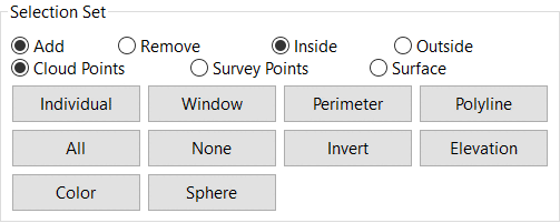
Add/Remove determines whether the objects that pass the criteria of the selection method are added or removed from the current selection set.There are also three radio buttons; Cloud Points, Survey Points and Surface which allows the user to operate on points contained within a Cloud/Scan, those imported in from manual survey work (e.g. GPS stakeout points) or a surface (TIN).
Inside/Outside determines whether to perform the selection operation on entities inside or outside the boundary of the current selection set.
There are four selection modes:
Individual, in which every mouse click attempts to select the object currently under the cursor - useful for precision selection of individual points.
Window in which the user clicks a base point and then clicks a second point that defines the opposite corners of a selection window.
Perimeter in which the user clicks several times to define the shape of the perimeter and then right-clicks to close the perimeter.
Polyline in which the user selects a polyline previously drawn in the scene using the create Polyline command.
There are also six global selection buttons:
All which selects all entities in the scene.
None which deselects all entities in the scene
Invert which inverts the current selection set within the scene.
Elevation where the user specifies a maximum and minimum elevation and the selection set is built from points between the specified elevations. Points outside the elevation range are ignored.
Color which selects all points with a matching RGB value to the point selected. Adjust the Color Tolerance to also select points with closely-matching RGB values. Users can Invert the Selection or Create a Region from it.
Sphere where any Points within the specified radius of the Specified Point Position will be selected. Adjust the Radius value to select more or less points.
A Region of selected Points can be saved to be hidden or to re-select at a later stage. See the Scene Tab page for more information.
The Edit panel contains controls for modifying the currently visible set of points.
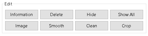
The Information button displays a properties
dialog with some general statistical information about the current
selection set, including the number of points selected, ranges of
their positions, color ranges and intensity values. Click Show
Advanced to display the Mean and Standard Deviation.
The Delete button deletes the selected points from the scene and from any objects that contained them. The User will be prompted to confirm whether to Delete selected entities. Once all Scenes containing that selection are closed, the user will be prompted to Modify existing, Create New or Discard Changes.
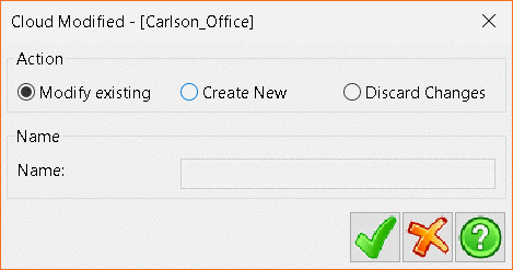
Modify existing will save the changes to the
original object (deleting points from the object as it is on disk,
which cannot be undone).
Create New will create a new object to save the
modified data and is typically the safer option because the
original data is still available if needed.
Discard Changes will close the scene without
saving your changes to the original object.
The Hide button temporarily hides the current
selection set, which isolates the current area of interest without
making permanent changes to the dataset.
Show All undoes all hide operations and will
revert to display all Points in the scene.
Image allows the user to drape an image over a mesh.
Smooth and Clean are functions performed on meshes only.The Transform panel contains four functions that allow for minor adjustments to be made to the selection set if required. Click any of the four buttons will display the Transform Cloud window.
![]()
Initially, the dialog will have no transformations specified. To
add a transformation, press the Green Plus button. which
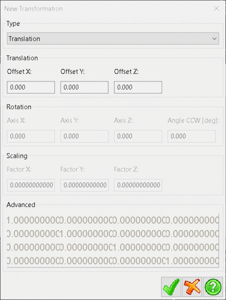
will open the New Tranformation window.
Use the Type drop-down menu to select one of the four
Transformation types:
Translate allows the user to define a translation of the current data set by specifying offsets in X, Y and Z.
Rotations allow the user to rotate the current selection set by specifying rotations around the X Y and Z axis.
Scaling allows the user to scale the current selection by a set Factor in the X, Y and Z axis.
Advanced allows the user to specify a transformation matrix to be applied to the data.
After clicking the check button you should be taken back to the
Transform Cloud window. From here you can add more
transformations, modify the currently selected one by pressing the
Green i button, delete them by pressing the
Red X button, or change their order of
application to the data using the Green arrow buttons. Press
the Green Tick button in the Transform
Cloud window to apply the transformations to the selected
data.
The transformation will be applied and a new Cloud created in the
Project Tree - the original Cloud will be
unaffected.
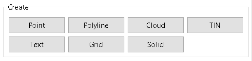
The Create Panel allows a user to manually create new project items either by specifying their points in the viewer (Point Polyline and Text) or by creating a new data set from the currently selected data points (Cloud, Mesh and Grid).
Clicking Point in the Create Panel will set the Current Mode to Point Creation and display the four panels that comprise the point creation mode.
Clicking Polyline in the Create Panel will set the Current Mode to Polyline Creation and display the four panels that comprise the polyline creation mode.
Clicking Cloud will bring up the standard Point Cloud creation dialog. In this case it will create a cloud with all the selected data in the current scene.
Clicking TIN in the Create Panel will bring up the standard TIN Creation dialog. In this case it will create a TIN with all the selected data in the current scene. However, one minor change is that the Normal panel has a From Scene option radio button which will make the mesh pull in its normal from the current camera's view direction. This allows you to view a scene of data and find an optimal viewing angle that gives the best results as a normal for the mesh.
Clicking Text in the Create Panel will set the Current Mode to Text Creation and display the two panels that comprise the text creation mode.
Clicking Grid in the Create Panel will bring up
the standard Grid
Creation dialog. In this case it will create a Grid with all
the selected data in the current scene.
Clicking Solid in the Create Panel will bring up the
Create Solid dialog. In this case it will create a Solid from
the selected data in the current scene.
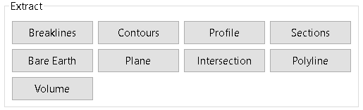
Each of the Extract functions are designed for use on a
processed specifically for either a processed TIN or cloud or
solid. Because of the complexity of each function has its own help
page.