This command allows you to modify TIN surfaces in a variety of different ways, then allows for 3D viewing and shading of the modified surface and finally for saving the file with a choice of output formats. The focus of the routine is to elevate or lower the TIN or selected areas within the TIN, merge TINs with other surfaces, or use data from other TIN files to apply to the current TIN.
Operations can be performed on the entire TIN or just on user selected Inclusion and/or Exclusion areas. The routine will automatically rework the TIN network for conformation to a selected boundary, say a building outline. In the case of said building, a value of 10 could be subtracted from the building outline. This will drop all of the triangulation within the outline by 10', thus creating a model of the excavated area for the building. The modified TIN can then be saved to a new file, which could be used to compute an excavation volume with Volumes by Triangulation. This routine does not allow for manual editing of individual portions of the TIN; refer to the editing options found under Surface Manager.
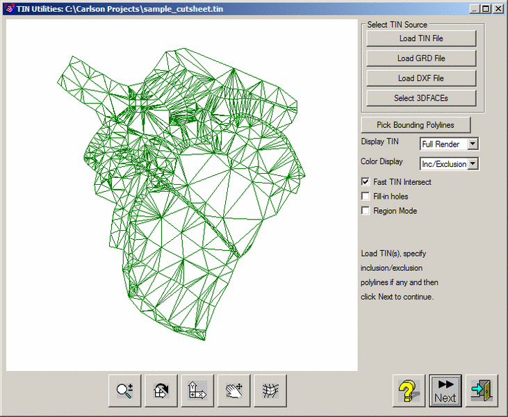
Load TIN File: Allows you to specify a triangulation (.flt or .tin) file to load.
Load GRD File: Allows you to specify a grid (.grd) file to load.
Load DXF File: Allows you to specify a DXF file to load. Only loads 3DFACE entities from the selected DXF file.
Select 3D Faces: Allows you to select 3DFACE entities from the current drawing. This also includes rectangular 3D faces from a plotted grid.
Pick Bounding Polylines: Allows you to select any inclusion/exclusion perimeter(s). When this button is selected, the user is taken back to the drawing and prompted to select the perimeters. Press Enter when the selections are finished to return back to the dialog.
Display TIN: Controls the detail level of the TIN in the graphic display. When the TIN is very large, the graphic display can cause delays. The Low Detail mode shows a simplified TIN graphic. The Outline Only mode shows only the TIN perimeter. The Full Render mode shows all the triangles.
Color Display: Displays the triangles based on whether or not they are part of the Inclusion/Exclusion set via the Pick Bounding Polylines option or colored based on the individual triangle color property.
Fast TIN Intersect: When checked, this command will perform a simple and fast check for overlapping triangles and is the preferred choice in most cases. However, if problems with the TIN are suspected, this option should be unchecked so a complete and thorough check and repair of the TIN is performed.
Fill-in-holes: When checked, any missing triangulation (or "gaps") in the surface will be automatically filled in with additional triangles. This option has to be set before loading the TIN file to take effect.
Region Mode: This option deals with nested or overlapping boundaries. When checked, "hatch pattern logic" is applied in which all nested boundaries are used in an alternating fashion, so that an Inclusion Boundary within an Exclusion Boundary is still recognized. If this option is not checked, everything within an Exclusion Boundary is ignored.
Next: Press this button to proceed to the next dialog after all selections have been made.
The next dialog allows you to perform mathematical operation(s) on the loaded TIN. Each operation is described below. Keep in mind that generally these operations are to be performed on an area inside your inclusion perimeter (but excluding anything inside your exclusion perimeters). If you do not specify any perimeters, the desired operation(s) will be performed on the entire TIN.
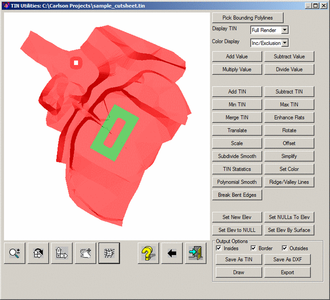
Add Value: Prompts for a value to Add to the elevations of the subject area of the TIN.
Subtract Value: Prompts for a value to Subtract from the elevations of the subject area of the TIN.
Multiply Value: Prompts for a value to Multiply to the elevations of the subject area of the TIN.
Divide Value: Prompts for a value to Divide into the elevations of the subject area of the TIN.
Add TIN: Raises the subject area of the current TIN by the elevation value from a second user-selected TIN file. This function is most applicable to applying a strata thickness (e.g. landfill cover) on top of a TIN to get a new target surface elevation.
Subtract TIN: Lowers the subject area of the current TIN by the elevation value from a second user-selected TIN file.
Min TIN: This does a comparison between the current TIN and a second user-selected TIN file and applies the lower value of the two TINs to the subject area.
Max TIN: This does a comparison between the current TIN and a second user-selected TIN file and applies the higher value of the two TINs to the subject area.
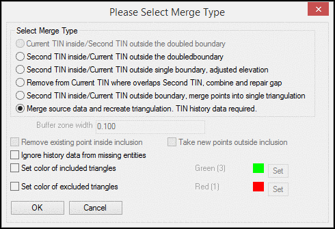
Merge TIN: Merges the current subject TIN into a second user-specified TIN file. There are six methods to merge tins. The methods for merging effect the way the gaps and elevation differences between the TINs are handled. If the two TINs being merged meet within a relatively close tolerance, the different methods will have little effect. In situations where the two surfaces being merged vary significantly, ie. an asbuilt of an area where the existing ground "tie in points' are also disturbed, the method of merging will be more obvious.
Enhance Flats: There are two method:
1. Interpolate Ridges, Valleys, Summits:
This routine eliminates flat triangles by adding a data point
inside the triangle at a different elevation to subdivide the
triangle. The elevation of this point is calculated based on the
slopes of the neighboring triangles.
2. Swap Edges to Minimize Flat Triangles:
This routine swaps edges of flat triangles when it can find a
neighboring point with a different elevation and still maintain the
triangulation.
Translate: This function has two methods:
Rotate: Rotates the TIN points by the specified rotation angle around a base point.
Scale: Scales the TIN points by the specified scale factor from a base point. The scale can be applied to just the x,y of the TIN points or the z, too. As an example, the Scale feature can be used to convert a TIN between Imperial and Metric units.
Offset: Performs a perpendicular offset (from the face/s) to the TIN surface by the specified amount. The routine offsets each point in the TIN vertically by looking at the slopes that connect to the point. For points at slope transition points such as at the bottom of a ditch, these corner points are effected by both slopes which means the program can't hold either exactly. To hold both slopes exactly would require changing the x/y position of the TIN points which this routine doesn't do to avoid more complications. So if the offset surface needs to exactly hold the slopes, then use another method like extracting Cross-sections from the Surface, offsetting these sections, creating 3D polylines from Sections and modeling the 3D polylines.
Smooth: There
are three methods to smooth the triangulation surface.
1. Subdivide : Performs a subdivision on the triangles
within a TIN for the intent of developing a smoother rendition of
the surface. This option is commonly used in scenarios where
surface models are derived from man-made data (e.g.
surfaces from contour maps, on-line sources, etc). The
routine starts to subdivide each triangle "n" times with each
iteration finding the centroid of the triangle. New triangles are
formed using this centroid location and the process
continues.
2. Polynomial
Smooth: This option uses a polynomial
interpolation in an effort to add additional points into the
surface model in an effort to produce a more "rounded" (less
man-made) surface.
3. Laplace: This method uses the
Laplacian method that adjusts each vertex using the positions of
the neighboring vertices.
Simplify: Causes edges within the TIN mesh to be collapsed to reduce the number of triangles, edges, and points within the TIN while having a minimal impact on the overall shape of the TIN. There are three methods:
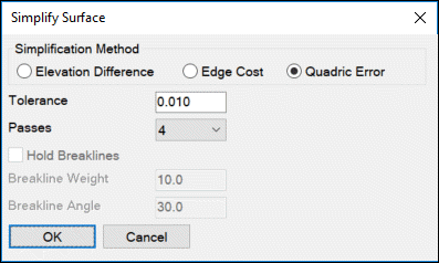 Tolerance: This setting is
used by both of the Simplification options described above. Specify
the maximum average distance that any point can be moved outside of
the plane of any triangle that connects to that point. Values might
range from .01 to .1 for most purposes.
Tolerance: This setting is
used by both of the Simplification options described above. Specify
the maximum average distance that any point can be moved outside of
the plane of any triangle that connects to that point. Values might
range from .01 to .1 for most purposes.
Passes: For the Elevation Difference option, this is the number of times the program will check through all the points.
Hold Breaklines: Further analyzes the TIN by focusing on the edges, calculating the angular difference between adjacent triangular faces. If the angular difference between edges is greater than the specified Breakline Angle, it is considered to be a breakline, and it is preserved. If its angular difference is determined to be below the Breakline Angle, it becomes a candidate for removal. In that case, the Breakline Weight factor is applied to the corresponding vertex, adjusting its original value. If the resulting value is still below the Tolerance, it is then removed. The number of vertices removed is inversely proportional to the Breakline Weight factor, so the greater the Breakline Weight factor, the fewer vertices that are removed, the lower the Breakline Weight factor, the more vertices that are removed.
TIN Statistics: Generates a report of the TIN statistics, including number of points, edges, and triangles, and minimum and maximum Z values.
Set Color: Assigns a selected color to the TIN triangles. The color is used when viewing the TIN file in the 3D viewer commands. To set the color within an inclusion perimeter, use the Pick Boundary Polylines option.
Ridge/Valley Lines: This option permits you to select previously drawn polylines that represent surface model breaklines to enhance the approximate appearance or effect of ridges and/or valleys within the surface model. A more precise procedure would be to first utilize the 3D Polyline routine and re-create the surface model by specifying the 3D polylines within the Triangulate & Contour routine.
Break Bent Edges: Used commonly in scenarios for a TIN created from contour
entities, there is a likelihood of areas where horizontal triangles
(also known as "flat triangles") adjoin sloped triangles. The
routine will detect such edges, add an additional point on the
horizontal triangles and assign its elevation representing the
trend of the surface, by extrapolation, looking to restore presumed
surface data that was lost in recreating the TIN from contours.
This methodology provides additional corrective options to that of
the Minimize
Flat Triangles option of the Triangulate
& Contour routine.
Set Elevation: This button has four
functions.
Set New Elev: Sets all TIN faces in the subject area to the elevation specified.
Set NULLs to Elev: Sets all NULL (empty) values in the subject area to the elevation specified.
Set Elev to NULL: Sets all of the elevation values in the subject area to NULL (empty).
Set Elev by
Surface: Sets all TIN faces within the
subject area to the elevations from a second surface file within
the same area. You will be prompted to select a second TIN file or
grid file. Only areas common to both surfaces will be applied to
the subject TIN.
Shrink-Wrap: This function removes
skinny triangles around the perimeter without causing any
triangulation points to become disconnected. There are three
reduction levels: low, medium and high. The low removes the fewest
triangles and high the most.
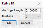
Refine: This function adds points to
the triangulation to make more uniform triangles and fewer skinny
triangles. The Min Edge Length prevents adding points that result
in an edge length below this minimum. The Interations is how many
passes the routine does through the triangulation.
Clean: This function removes
triangulation points that are within the specified distance and
then re-triangulates the surface.
The following three options determine what part or parts of the TIN modifications that will be saved to the new TIN file. If the entire TIN is to be saved, all three options should be enabled.
Save: Saves the current TIN as an .flt or .tin file.
Draw: Draws the current TIN as 3D Faces in the current viewport. The Layer window is used to specify the layer that the faces will be created in.
Export: There
are three export formats:
1. Export To Text (points only): Writes the TIN
point locations to a user-specified ASCII-based coordinate
file.
2. Export To Text (points and triangles):
Outputs a text file of the points and triangle indexes.
3. Export To DXF: Saves the current TIN as a .dxf file. This format can be
used by many other CAD programs.
| Control | Action |
|---|---|

|
Converts the left mouse button to a zoom function. Hold the button down and move the mouse up or down to zoom in and out. |

|
Converts the left mouse button to a rotate function. Hold the button down to rotate the view in any X, Y or Z direction. When the XY appears in the window, the rotation will occur relative to the XY axis. When the mouse is moved toward the outer perimeter of the window, the XY will change to a Z. Holding the button down while the Z is visible will rotate the drawing on the Z axis. |

|
Restores the graphics to plan view. |

|
Converts the left mouse button to a pan function. Hold down on the button while moving the mouse to pan. Holding down the mouse wheel will also serve as a pan function in any of the above modes. |

|
Toggles shading on and off. |

|
Reverses the effects of all operations performed on the TIN and reverts it back to its original status. |

|
This icon exits the routine. If the TIN has been modified, you will be prompted to save. |
Pulldown Menu Location(s):
Surface
Keyboard Command: tinutil
Prerequisite: 3D Faces, a TIN file or a DXF file containg
3DFACE entities.